


7. Close the drain valve. Open the nearest hot water
faucet and allow the tank to fill completely with
water. To purge the lines of any excess air and
sediment, keep the hot water faucet open for 3
minutes after a constant flow of water is obtained.
8. Check for leaks around the element(s).
9. Connect the electric wires to the heater element.
Make sure all wires are secure.
10. Replace the insulation and access door(s).
Important: Operation of this water heater without
access doors or insulation could result in much higher
temperatures than the desired set point, increasing the
risk of scald injury. Do not operate water heater with the
access doors or insulation removed.
11. Make certain the tank is filled with water.
12. Restore the electric power supply to the water
heater.
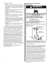
Electrical Shock Hazard
Disconnect power before
servicing.
Replace all parts and panels
before operating.
Failure to do so can result
in death or electrical shock.
Replacement heating elements must be of the same
style and voltage/wattage rating as the ones presently
in the water heater. This information can be found on
the flange or terminal block of the element or on the
water heater data plate.
1. Shut off the electric power to the water heater.
2. Drain the water heater as directed under "Draining
and Flushing".
3. Remove the access door(s), insulation and element
cover(s).
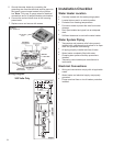
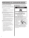
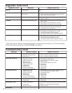
4. Disconnect the electric wires from the heating
element (Figure 9). Remove the screw-in elements
by turning the element counterclockwise with an
1-½ inch socket wrench. Remove the existing
gasket.
5. Clean the area where the gasket fits to the tank. If
you are replacing the bottom element, remove the
accumulated sediment on the bottom of the tank.
Refer to “Draining and Flushing.”
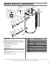
6. Make sure the replacement element has the correct
voltage and wattage rating. Position the new gasket
on the element and insert it into the water heater
tank (Figure 10). Tighten the element by turning it
clockwise until secure.
Heating Element
Replacement
13
WARNING
Figure 10
Element and Temperature
Sensor
Spud
Screw-in
Element
Gasket
Temperature Sensor
Sensor
Bracket
Ground
Wire (green)
Figure 9
Element Wiring
Connection
Screws
Wires
Element