


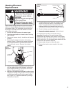
Temperature and Pressure
Relief Valve
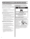
For protection against excessive pressures and
temperatures, a temperature and pressure relief valve
must be installed in the opening marked “T & P RELIEF
VALVE” (See Figure 5).
Caution: To reduce the risk of excessive pressures and
temperatures in this water heater, install temperature
and pressure relief protective equipment required by
local codes, but not less than a combination
temperature and pressure relief valve certified by a
nationally recognized testing laboratory that maintains
periodic inspection of the production of listed equipment
or materials, as meeting the requirements for Relief
Valves and Automatic Shutoff Devices for Hot Water
Supply Systems, ANSI Z21.22 -1986. This valve must
be marked with the maximum set pressure not to
exceed the marked maximum working pressure of the
water heater. Install the valve into an opening provided
and marked for this purpose in the water heater, and
orient it or provide tubing so that any discharge from the
valve exits only within 6 inches above, or at any
distance below, the structural floor, and does not
contact any live electrical part. The discharge opening
must not be blocked or reduced in size under any
circumstance.
Please note the following:
DO NOT install this water heater with iron piping.
The system should be installed only with new piping
that is suitable for potable (drinkable) water such as
copper, CPVC, or polybutylene. DO NOT use PVC
water piping.
DO NOT use any pumps, valves, or fittings that are
not compatible with potable water.
DO NOT use valves that may cause excessive
restriction to water flow. Use full flow ball or gate
valves only.
DO NOT use 50/50 tin-lead solder (or any lead
based solder) in potable water lines. Use 95/5 tin-
antimony or other equivalent material.
DO NOT tamper with the electronic control board,
temperature sensors, heating elements, electrical
connections, or temperature and pressure relief
valve. Tampering voids all warranties. Only qualified
service technicians should service these
components.
DO NOT use with piping that has been treated with
chromates, boiler seal, or other chemicals.
DO NOT add any chemicals to the system piping
which will contaminate the potable water supply.
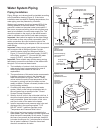
Closed System/Thermal Expansion
Periodic discharge of the temperature and pressure
relief valve may be due to thermal expansion in a
closed water supply system. The water utility supply
meter may contain a check valve, backflow preventer,
or water pressure reducing valve. This will create a
closed water system. During the heating cycle of the
water heater, the water expands causing pressure
inside the water heater to increase. This may cause the
temperature and pressure relief valve to discharge
small quantities of hot water. To prevent this, it is
recommended that a diaphragm-type expansion tank
(suitable for potable water) be installed on the cold
water supply line. The expansion tank must have a
minimum capacity of 1.5 U.S. gallons for every 50
gallons of stored water. Contact the local water supplier
or plumbing inspector for information on other methods
to control this situation.
Do not plug or remove the temperature and
pressure relief valve.
6
WARNING
Explosion Hazard
If the temperature and pressure relief
valve is dripping or leaking, have a
qualified service technician replace it.
• Do not plug valve.
• Do not remove valve.
Failure to follow these instructions can
result in death or explosion.
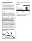
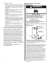
Figure 5
Temperature and Pressure
Relief Valve Installation
Optional location some
models only
Temperature and
Pressure Relief Valve
Discharge Line
3/4 inch min.
Do not cap or plug.
6 inch
maximum
Drain Pan
Drain