


4
BCP-3 Installation and Operation Manual
IMPORTANT
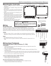
Determining the proper location for the Outdoor Sensor is very important.
The BCP-3 will base the heat on the outdoor temperature information it
receives from this location. If the sensor is in the sun, or covered with
ice, its reading will be different from the actual outdoor temperature.
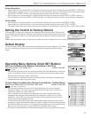
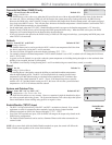
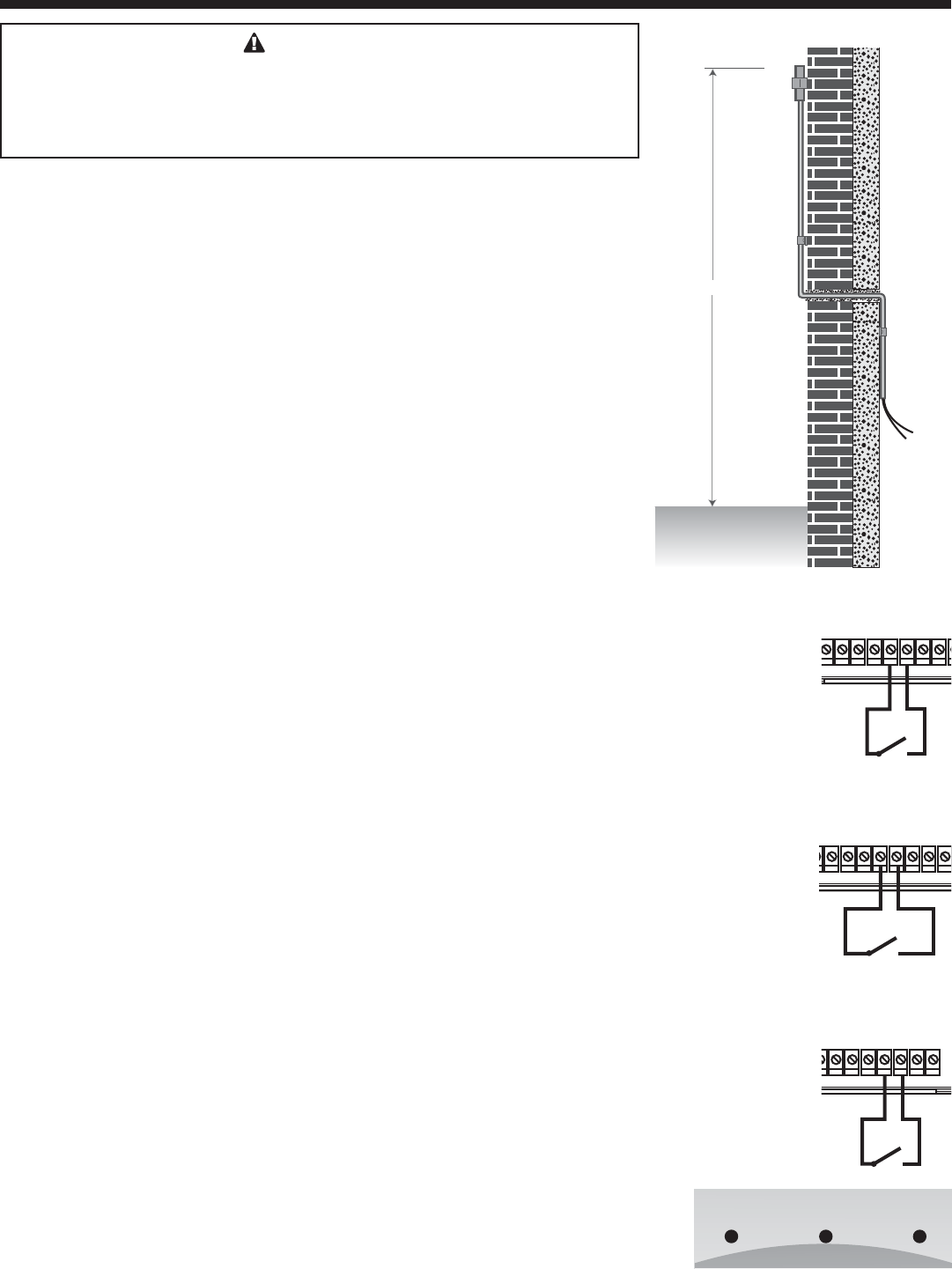
Outdoor Sensor Installation (T2, COM)
• The Outdoor Sensor must be used when Outdoor Reset is selected as the Control Mode
from the Startup menu. However, in Set Point mode, the Outdoor Sensor is optional.
When connected in that mode, it will be used as an input for the Outdoor Cutoff only.
• Only use the Weil McLain sensor included with the unit.
• Place the sensor in the shade on the north side of the building.
• Be sure the location is away from doors, windows, exhaust fans, vents, or other heat
sources.
• The sensor should be mounted approximately 10' feet above ground level.
• Mount the sensor clip base to the outside of the building. Insert the sensor in the middle
and snap close the second clip on the sensor.
• The sensor wires can be extended up to 500' using shielded 2-conductor cable.
• Cut the shield and do not connect it at the sensor end. Only connect it at the control end
using the outdoor terminal marked COM.
• Do not run sensor wires in conduit with line voltage wiring.
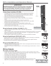
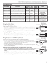
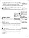
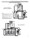
Wiring the Domestic Hot Water Call DHW (T3+, T3-)
• A DHW call will raise system Set Point to 200°F or Maximum Target temperature,
whichever is lower.
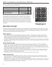
• When "1-On/Off+2-Pump" is selected as the Output Mode from the Startup menu, the BCP-3 can control the
operation of the Domestic Hot Water (DHW) pump using Output 3. See Output Mode Table on page 4.
• DHW Call terminals are dry contact N.O. terminals.
• Wire an aquastat or another control to provide dry contact closure on the DHW Call terminals.
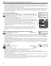
Wiring the Enable/Disable (TSTAT) (EXT+, EXT-)
• The EXT terminals can be used to enable or disable the heat to the system by connecting it to a thermostat,
external control, or a switch. It accepts dry contact input only.
• If no thermostat or control is connected to the EXT terminals, leave the jumper supplied connected.
• No outputs will be active unless the EXT terminals are closed/shorted.
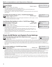
Wiring the Setback/Boost (P+, P-)
• The Setback feature can be used to provide the BCP-3 with a lower temperature Set Point when less heat is
required during night or unoccupied periods.
• The Setback is activated by closing/shorting the P+ and P- terminals using an external control, i.e. timer or
switch.
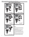
Wiring Outputs
Wire Colors and Output Lights
• The BCP-3 has a three S.P.S.T. (N.O.) output relays. Each relay is rated at 1A Inductive load (1/8 HP).
• The BCP-3 has three LED lights that follow the output relays' operation. When a relay energizes, its LED
will turn on. When the relay de-energizes, its LED will turn off.
• The outputs are dry contacts only. They do not source any power.
• The two Yellow wires represent Output 1 relay and the left LED.
• The two Blue wires represent Output 2 relay and the middle LED.
• The two White wires represent Output 3 relay and the right LED.
• Depending on the Output Mode of operation selected during the Startup, the function of each
output will vary. See Output Mode Table for output wire colors and functions on page 4.
10' Minimum
Outdoor Sensor
Low Voltage
Sensor Wires
Sensor Clip
T3+
COM
T3-
EXT+EXT-
P+ P-
COM
Enable/Disable
Wiring
T
1 T2 T3+
COM COM
T3-
EXT+EXT-
DHW Call
Wiring
3
+ T3-
EXT+EXT-
P+ P-
COM 24VAC
Setback/Boost
Wiring
Boiler
SYS
Pump
DHW
Pump
Output 1 Output 2 Output 3