


15
BCP-3 Installation and Operation Manual
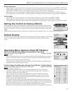
Boiler1
DHW
Indirect
Building
Heat
System
Sensor
Outdoor
Sensor
T1
T2
COM
COM
T3+
T3-
EXT+
EXT-
P+
P-
COM
24VAC
} System Sensor
} Outdoor Sensor
} DHW Call Dry Contact
} Enable Dry Contact
} Setback Dry Contact
Boiler
SYS
Pump
DHW
Pump
SET
SET
SYSTEM = 147F
TARGET = 150F
Yellow Wires (Output 1)
Blue Wires (Output 2)
Boiler2 Boiler3
System
Pump
White Wires
(Output 3)
DHW
Pump
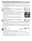
Boiler
DHW
Indirect
Building
Heat
System
Pump
System
Sensor
Outdoor
Sensor
T1
T2
COM
COM
T3+
T3-
EXT+
EXT-
P+
P-
COM
24VAC
} System Sensor
} Outdoor Sensor
} DHW Call Dry Contact
} Enable Dry Contact
} Setback Dry Contact
Boiler
SYS
Pump
DHW
Pump
SET
SET
SYSTEM = 147F
TARGET = 150F
DHW Pump
Yellow Wires (Output 1)
Blue Wires (Output 2)
White Wires (Output 3)
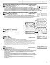
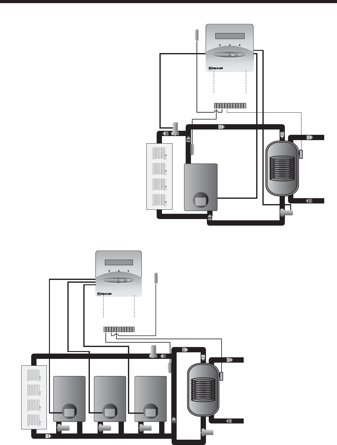
Piping 1 On/Off Boiler +
System Pump + DHW Pump
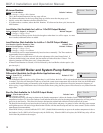
Piping 3 On/Off Boilers
Aquastat
Aquastat
BCP-3
BCP-3
Output 1 Output 2 Output 3
Output 1 Output 2 Output 3
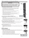
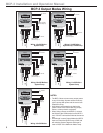
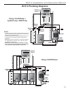
BCP-3 Plumbing Diagrams
NOTES:
• The BCP-3 does not source any output power to any of its
relays. A power source must supply pumps with power and
the control can break the hot leg.
• Weil McLain recommends using a separate power source
to the control from any pumps, boilers, heavy electric
equipment.
• When wiring a sensor to the BCP-3, connect the Shield to
the COM terminal on the BCP-3 end. DO NOT connect
the Shield at the sensor end.
• Weil McLain is aware that each installation is unique.
Thus, any wiring or piping diagrams in this document
are to represent control operation concept only.