


6
GAS INSTRUCTIONS
Table
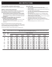
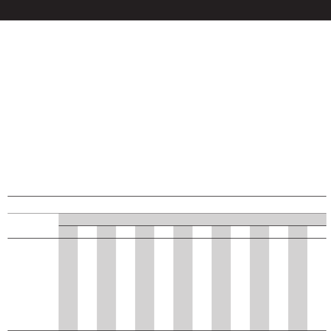
10-1
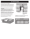
Maximum Capacity of Pipe in Cubic Feet of Gas per Hour for Gas Pressures of 0.5 psi or Less and a Pressure Drop of 0.3 Inch
Water Column. (Based on a 0.60 Specifi c Gravity Gas)
Nominal
Iron Pipe
Size
(Inches)
Internal
Diameter
(Inches)
Length of Pipe (Feet)
10 20 30 40 50 60 70 80 90 100 125 150 175 200
1/4 .364 32 22 18 15 14 12 11 11 10 9 8 8 7 6
3/8 .493 72 49 40 34 30 27 25 23 22 21 18 17 15 14
1/2 .622 132 92 73 63 56 50 46 43 40 38 34 31 28 26
3/4 .824 278 190 152 130 115 105 96 90 84 79 72 64 59 55
1 1.049 520 350 285 245 215 195 180 170 160 150 130 120 110 100
1 1/4 1.380 1050 730 590 500 440 400 370 350 320 305 275 250 225 210
1 1/2 1.160 1600 1100 890 760 670 610 560 530 490 460 410 380 350 320
2 2.067 3050 2100 1650 1450 1270 1150 1050 990 930 870 780 710 650 610
2 1/2 2.469 4800 3300 2700 2300 2000 1850 1700 1600 1500 1400 1250 1130 1050 980
3 3.068 8500 5900 4700 4100 3600 3250 3000 2800 2600 2500 2200 2000 1850 1700
4 4.026 17500 12000 9700 8300 7400 6800 6200 5800 5400 5100 4500 4100 3800 3500
©1997 National Fire Protection Association, Inc., and International Approval Services - U.S., Inc. All Rights Reserved.
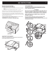
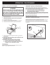
TYPICAL NATURAL GAS SUPPLY INSTALLATION
We recommend that this installation be done by a LICENSED professional.
GENERAL SPECIFICATIONS FOR PIPING
Note - Contact your local municipality for building codes regulating outdoor
gas grill installations. In absence of Local Codes, you must conform to the
latest edition of National Fuel Gas Code ANSI Z223.1/NFPA54.
• This grill is designed to operate at 4.5 inches of water column pressure.
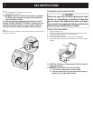
• A manual shut-off valve must be installed outdoors, and be accessible,
not in the “built-in” structure. An additional manual shut-off valve indoors
should be installed in the branch fuel line in an accessible location near
the supply line.
ƽ CAUTION: If young children are in the area, a
locking valve should be considered.
• Pipe compound should be used which is resistant to the action of liquid
propane gas when gas connections are made.
• The gas connections must be fi rmly attached to a rigid, permanent
construction.
Note: The information provided in this manual is general for typical
installations. We cannot cover all possible installation ideas. We recommend,
prior to installation, that you contact your municipality for local building codes
and your local fi re department for installation verifi cation.
If you have any questions, contact Customer Service at 1-800-446-1071.
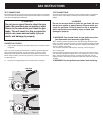
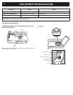
GAS LINE PIPING
• Refer to the piping chart at the bottom of previous page.
• The corrugated gas line from the manifold is 58 inches long. Do not
extend the gas line.
• We have provided the means to make an SAE 45° fl are connection. Do
not use pipe sealant on this connection.
• If the length of line required does not exceed 50 feet, use a 5/8” O.D.
tube. One size larger should be used for lengths greater than 50 feet.
Refer to piping chart.
• Gas piping may be copper tubing, type K or L; polyethylene plastic
tube, with a minimum wall thickness of .062 inch; or standard weight
(schedule 40) steel or wrought iron pipe.
• Copper tubing must be tin-lined if the gas contains more than 0.3 grams
of hydrogen sulfi de per 100 cubic feet of gas.
• Plastic tubing is suitable only for outdoor, underground use.
• Gas piping in contact with earth, or any other material which may
corrode the piping, must be protected against corrosion in an approved
manner.
• Underground piping must have a minimum of 18” cover.