


5INSTALLATION WEBASTO THERMO 300
5-4
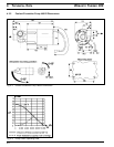
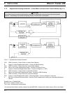
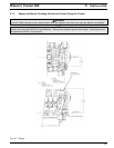
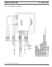
Fig. 5-1: Supplemental Heating Schematic
5.7.2 Supplemental Heating Schematic - Jacket Water and Intercooler Coolant Heaters (fig. 5-1)
CAUTION
The coolant pump(s) must be operating and a continuous unobstructed coolant path provided during heater
operation. Overheating of the heater will quickly develop if coolant flow is interrupted.
CO2: OEM Connection - Engine Outlet to Jacket Water Radiator
B: Supply to Jacket Supplemental Heater - Connect to OEM Plumbing
CO1: OEM Connection - Engine Inlet from Jacket Water Radiator
CO5: Return from Jacket Supplemental Heater - Connect to Engine (30 mm)
E: Supply to Intercooler Supplemental Heater - Connect to Engine (1 in. NPT)
IC2: OEM Connection - Engine Outlet to Intercooler Radiator
G: Return from Intercooler Supplemental Heater - Connect to OEM Plumbing
IC1: OEM Connection - Engine Inlet from Intercooler Radiator
CO3: Supply to Jacket Supplemental Heater - Preheating Mode - Connect to Engine (2 X 20 mm)
K: Ball valve or Solenoid Activated Valve - Required if both Supplemental Heating and Preheating Modes are
Desired
Dashed Lines = Preheat Mode
Bold Lines = Engine Coolant Circuit
Thin Lines = Supplemental Heating Mode
* All presures listed without radiator pressure cap @ 1900 RPM - pressure with radiator cap on will be 1 bar higher.