


WEBASTO THERMO 300 5INSTALLATION
5-3
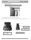
For a straight connection, order a straight adapter under part number 101377 and snap it onto the combustion air
inlet and attach air ducting.
In the event there is insufficient room for a straight attachment, a 90° snap-on fitting (P.N. 101404) and an adapter
ring (P.N. 82315A) are available. Simply snap them onto the combustion air inlet of the heater and attach ducting.
For installations where ducting is not required, the heater is factory equipped with a splash deflector that simply snaps
onto the combustion air inlet.
NOTE:
Webasto approved flexible combustion air ducting is available from your Webasto Thermosystems supplier under
part number 88729A.
5.7 Plumbing Into the Coolant System
5.7.1 General Information
The coolant circulating pump must be mounted as low as possible in the vehicle’s cooling system. A minimum of
10% of a good quality antifreeze should be maintained in the cooling system at all times. Heater and water pump fit
1.5” (38 mm) I.D. heater hose meeting SAE 20 R3 specifications. Silicone hose requires special hose clamps.
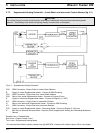
Refer to “Supplemental Heating Schematic - Jacket Water and Intercooler Coolant Heaters” under section 5.7.2 for
information regarding plumbing the coolant heater into the coolant system.
WARNING
Burn risk! When working on the coolant system, allow the engine to cool down and open the radiator cap carefully.
CAUTION
The coolant pump(s) must be operating and a continuous unobstructed coolant path provided during heater
operation. Overheating of the heater will quickly develop if coolant flow is interrupted.
NOTE:
Heater hose must meet SAE 20 R3 specifications. Silicone hose requires special hose clamps. Hose clamps must
be tightened to 45 lb/in. (5 Nm) torque.