


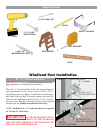
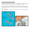

Slide the windload post(s) into storage header bracket(s)
and secure the bottom strap(s) to the half hinge(s) using
the 3-1/2” carriage bolt and wing nut. Place all remaining
wing nuts and carriage bolts into the remaining straps for
storage. Insert plastic plug into hole in fl oor.
Securing Post for Storage
Locate a convenient place to store the windload post(s).
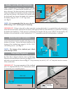
Measure and cut (2) 2” x 6” wood mounting blocks a
minimum of 10” long for each windload post. Locate
the mounting blocks horizontally on the wall as shown
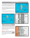
in Fig. 12. Secure them adequately to the wall at the top
and bottom of the post storage location, with masonry
anchors for concrete construction, or 16 penny nails for
wood construction. Measure a distance of 6” greater than
door height as illustrated in Fig. 12, and mount the extra
header lock bracket(s) to the top mounting block(s) using
(2) 5/16” x 1-5/8” lag screws as shown in Fig. 12.
Measure the distance from the top of the windload post
to the center of the bottom strap (see Fig. 13). Use that
measurement for the dimension between the center of
the extra header lock bracket and half-hinge tube. Posi-
tion the half-hinge on the bottom mounting block and
secure the half-hinge using (2) 5/16” x 1-5/8” lag screws.
Repeat this step for remaining windload posts if neces-
sary. (see Fig. 12)
7
6” MIN.
(2) 5/16” X 1-5/8”
LAG SCREWS
(2) 5/16” X 1-5/8”
LAG SCREWS
HEADER LOCK
BRACKET
HALF-HINGE
TUBE
DISTANCE BETWEEN TOP
OF WINDLOAD POST AND
CENTER OF BOTTOM
STRAP
FIG. 12
MEASURE THE
DISTANCE FROM THE
TOP OF THE WINDLOAD
POST TO THE CENTER
OF THE BOTTOM STRAP
TOP OF WINDLOAD POST
BOTTOM OF
WINDLOAD POST
BOTTOM
STRAP
FIG. 13
HALF
HINGE
JR. “A”
FRAME