


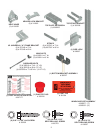

Required Tools
3
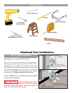
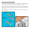
JR. “A” Frame Installation
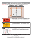
IMPORTANT! Refer to the windload specifi cation draw-
ings (supplied) for windload post location(s).
Place the “A” frame brackets below the center hinges of
each intermediate section, fasten with (2) 1/4-20 x 11/16”
self drilling screws (see Fig.1). For the bottom section, align
half hinge with top edge of astragal retainer and center on
stile(s). Fasten half hinge with (4) 1/4-20 x 11/16” self-drill-
ing screws (see Fig.1A). Center all brackets in the required
positions per the windload specifi cation drawings.
NOTE: Additional Jr. “A” frame brackets are required
for 10’ and 12’ wide doors.
WARNING
“A” FRAME BRACKETS MUST
BE INSTALLED ACCORDING TO THE WINDLOAD
SPECIFICATION DRAWINGS, OR DOOR FAILURE
WILL OCCUR UNDER WINDLOAD
.
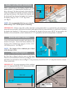
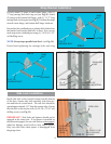
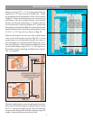
Windload Post Installation
(2) 1/4-20 X 11/16”
SELF-DRILLING SCREW
FIG. 1
FIG. 1A
(1) 3/16” DRILL BIT
(1) 7/16” HEX
HEAD DRIVER
DRILL
STEP LADDER
PENCIL
TAPE MEASURE
SAFETY GLASSES
LEVEL
(1) 5/8” X 4”
MASONRY DRILL BIT
JR. “A” FRAME
(4) 1/4-20 X 11/16”
SELF-DRILLING SCREW
CENTER HINGE
HALF HINGE
EDGE OF
ASTRAGAL RETAINER