


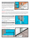
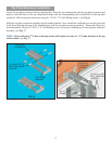

Bottom Bracket Installation
Locate the bottom bracket assembly and align it to the
bottom of the post. Secure the bottom bracket to the
bottom of the windload post using (4) 1/4-20 x 11/16”
self-drilling screws. (see Fig. 3)
NOTE: The bottom of the windload post is fl ush
while the top is offset.
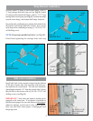
At each windload post location, mark a center line on
the fl oor that is aligned with the center of half hinge.
Measure out from the back of the door (see Fig. 4) 5-3/4”
and make a second mark as shown in Fig. 5. Using a masonry bit, drill (1) 5/8” x 4” deep hole into the concrete.
Clean out the hole.
IMPORTANT! For proper operation of the windload
post, it is important that the 5-3/4” dimension be held,
to assure the post is installed plumb.
Post Hole Placement
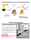
Header Lock Bracket Installation
Mark a vertical line on the header, aligned with the
center of the Jr. “A” frame bracket. Measure up 1-1/2”
above the top of the door and mark a horizontal line.
Center the header lock bracket with the vertical line
and align the bottom of the header lock bracket with
the horizontal line. Secure the header lock bracket to
the header using (4) 5/16” x 1-5/8” lag screws.
(see Fig. 2)
NOTE: It is recommended that lag screws be pilot
drilled using a 3/16” drill bit prior to fastening.
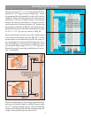
IMPORTANT! If there is drywall or other materials covering the header it is required that such materials be
removed from the header lock bracket location(s) and replaced with the same thickness of wood before installing
the header lock bracket(s). If this process is performed, the length of the lag screws MUST be increased by the
thickness of wood material, so that a minimum of 1-1/2” penetration into the existing header is obtained.
4
CENTER LINE
OF HALF HINGE
5/8” X 4”
DEEP HOLE
(4) 1/4-20 X 11/16”
SELF-DRILLING
SCREWS
BOTTOM
BRACKET
ASSEMBLY
DIM. 5-3/4”
FIG. 3
FIG. 4
(4) 5/16” X 1-5/8”
LAG SCREWS
HEADER LOCK
BRACKET
HEADER
FIG. 2
1-1/2”
CENTER
LINE
DIM. 5-3/4”
FIG. 5
DO NOT MEASURE
FROM BOTTOM SEAL
(SEE FIG.4)