


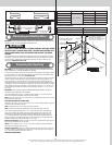

INSTALLATION
Before installing your door, be certain that you have read and followed all of the instruc-
tions covered in the pre-installation section of this manual. Failure to do so may result in an
improperly installed door.
IMPORTANT: WOOD DOORS MUST BE COMPLETELY FINISHED (3 TOTAL COATS, INCLUDING
PRIMER COAT) PRIOR TO INSTALLATION, TO ENSURE THAT THE INTERIOR AND EXTERIOR
SURFACES, AS WELL AS ALL EDGES OF THE DOORS ARE PROPERLY PROTECTED AGAINST
MOISTURE OR OTHER CONTAMINANTS. WOOD DOORS, IN A NON-FINISHED CONDITION,
MUST BE TRANSPORTED AND STORED SO THE WOOD SURFACES ARE NOT EXPOSED
TO MOISTURE OR OTHER CONTAMINANTS. IMPROPER TRANSPORTATION, STORAGE OR
DELAYS IN FINISHING, THAT ALLOWS EXPOSURE OF THE WOOD DOOR SURFACES TO MOIS-
TURE OR OTHER CONTAMINANTS WILL RESULT IN THE WARRANTY BEING VOIDED.
NOTE: Reference TDS 160 for general garage door terminology at www.dasma.com.
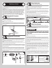
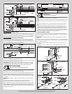
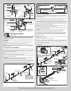
Fully Adjustable Flag Angles
Tools: None
1
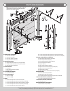
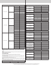
NOTE: If you have a wall angle track assembly or if you already have flag angles pre-
attached to the vertical tracks, skip this step. Refer to Package Contents / Parts Breakdown,
to determine if you have flag angles.
NOTE: Flag angles are right and left handed.
If you have Fully Adjustable vertical tracks, hand tighten the left hand flag angle to the left
hand vertical track using (2) 1/4”-20 x 9/16” track bolts and (2) 1/4”-20 flange hex nuts.
Repeat for other side. Flange nuts will be secured after flag angle spacing is completed in
step, Top Section.
1/4”- 20 x 9/16”
Track bolts
Flag angle
Fully Adjustable
vertical
track
1/4”-20
Flange hex nuts
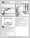
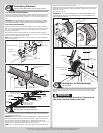
Fully Adjustable Jamb Brackets
Tools: None
2
NOTE: If you have a wall angle track assembly or if you already have jamb brackets pre-
attached to the vertical tracks, skip this step. Refer to Package Contents / Parts Breakdown,
to determine if you have jamb brackets.
NOTE: The bottom jamb bracket is always the shortest bracket, while the center jamb
bracket is the next tallest. If three jamb brackets per side are included with your door, you will
have received a top jamb bracket, which is the tallest.
To attach the bottom jamb bracket, locate lower hole of the hole/ slot pattern of the 1st hole
set on the vertical track. Align the slot in the jamb bracket with the lower hole of the hole/ slot
pattern. Secure jamb bracket using (1) 1/4”-20 x 9/16” track bolt and (1) 1/4”-20 flange hex
nut. Repeat for other side.
Place the center jamb bracket over the lower hole of the hole/ slot pattern that is centered
between the bottom jamb bracket and flag angle of the 2nd hole set. Secure jamb bracket
using (1) 1/4”-20 x 9/16” track bolt and (1) 1/4”-20 flange hex nut. Repeat for other side.
If a top jamb bracket was included, secure it to vertical track using the lower hole of the hole/
slot pattern in the 3rd hole set and (1) 1/4”-20 x 9/16” track bolt and (1) 1/4”-20 flange hex
nut. Repeat for other side.
F.A. jamb
bracket
1/4”- 20 x
9/16”
Track bolt
1/4”- 20
Flange hex nut
Jamb bracket
in place
1st hole set
Lower hole of
hole/ slot pattern
Vertical track
2nd hole set 3rd hole set
Top of track
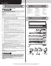
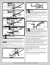
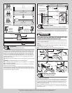
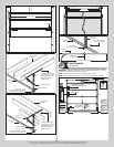
Bottom Weather Seal
Tools: Hammer, Tape Measure, Saw Horses
3
NOTE: If a bottom weather seal is supplied, complete this step.
NOTE: Refer to Door Section Identification / Parts Breakdown.
Place the bottom section face down on a couple of sawhorses or flat clean/ smooth surface.
Align the bottom weather seal with the flap pointing towards the outside surface of the bot-
tom section.
Starting at one end of the door, measure inward 1” and attach the bottom weather seal to
the bottom of the bottom section with 3/4” long galvanized roofing nails (not supplied). Now
stretch the bottom weather seal slightly and nail the rest of the bottom weather seal to the
bottom of the bottom section every 6”.
Once the bottom weather seal is fastened cut off any extra material so that the bottom
weather seal is even with both ends of the bottom section.
NOTE: Verify bottom weather seal is aligned with bottom section. If there is more than 1/2”
excess weather seal on either side, trim weather seal even with bottom section.
Edge of
bottom
section
Side
view
bottom
section
3/4” Long galvanized roofing nails (not supplied)
1”
6”
6”
Bottom
weather seal
Flap
Bottom
weather
seal
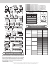
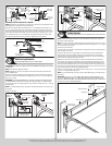
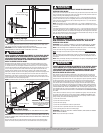
Bottom Corner Brackets
Tools: Power Drill, 9/32” Drill Bit, Socket Driver 7/16”, Wrench 7/16”
4
NOTE: Refer to Door Section Identification / Parts Breakdown, to determine which bottom
corner brackets were supplied with your door.
WARNING WARNING
FAILURE TO ENSURE TIGHT FIT OF CABLE LOOP OVER COTTER PIN OR MIL-
FORD PIN COULD RESULT IN COUNTERBALANCE LIFT CABLE COMING OFF
THE PIN, ALLOWING THE DOOR TO FALL, POSSIBLY RESULTING IN SEVERE
OR FATAL INJURY.
With the bottom section facing down from the previous step, uncoil the counterbalance lift
cables.
Starting on the left hand side, either:
Place the cable loop into position between the two holes on the side of the left hand bottom
corner bracket. Slide a clevis pin through the innermost hole, cable loop, and outermost
hole, of the bottom corner bracket. Slide a washer onto the clevis pin and secure in place by
inserting a cotter pin into the hole of the clevis pin. Bend the ends of the cotter pin outwards
to secure it in place. Repeat for other bottom corner bracket.
Place the cable loop on the milford pin of the bottom corner bracket. Repeat for other bottom
corner bracket.
Next, starting on the left hand side, align the left hand bottom corner bracket horizontally with
the bottom edge of the bottom section and also align the bottom corner bracket vertically
with the left bottom edge of the bottom section. Using the bottom corner bracket as a tem-
plate, mark and pre-drill 9/32” diameter holes through the bottom section. Attach the bottom
corner bracket to the bottom section using 1/4”-20 x 1-7/8” carriage bolts and 1/4”–20
flange hex nuts, as shown. Repeat the same process for other side. Mark and drill a pilot
holes 1” deep into the bottom section with a 1/8” drill bit. Secure the bottom corner brackets
to the bottom section using (1) 1/4”-14 x 1” tamper resistant lag screw, as shown. Repeat
the same process for the right hand side.
IMPORTANT: BE EXTREMELY CAREFUL NOT TO DRILL THRU THE SECTION. ONLY DRILL 1”
DEEP.
NOTE: All doors are provided with the tamper resistant fastener for the bottom corner brack-
ets. However, the professional installer is most likely to have the proper tool to install this fas-
tener. If the homeowner does not have the proper tool to install the tamper resistant fastener,
use a regular 1/4”-20 x 1-7/8” carriage bolt and a 1/4”–20 flange hex nut in its place.
If applicable, insert a short stem track roller into each of the bottom corner brackets, as
shown.
Counterbalance lift cable loop
Cotter pin (attached into
place from opposite side
of bottom corner bracket)
Clevis pin (inserted through cotter pin
and bent into place)
Washer
Typical left hand
bottom corner bracket
Typical left
hand bottom
corner bracket
Please Do Not Return This Product To The Store. Contact your local Wayne-Dalton dealer. To find your local Wayne-Dalton dealer,
refer to your local yellow pages business listings or go to the Find a Dealer section online at www.Wayne-Dalton.com
7