


Please Do Not Return This Product To The Store. Contact your local Wayne-Dalton dealer. To find your local Wayne-Dalton dealer,
refer to your local yellow pages business listings or go to the Find a Dealer section online at www.Wayne-Dalton.com
Torsion Spring Attachment
Tools: Step Ladder, Ratchet Wrench, 9/16” Socket, 9/16” Wrench
20
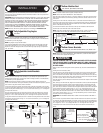
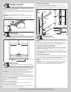
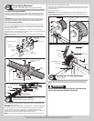
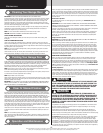
IF YOU DON’T HAVE A COUPLER ASSEMBLY:
Slide the center bracket bushing into the center bracket. Align the stationary spring cone(s)
with the holes in the center bracket bushing assembly. Secure the torsion spring(s) to the
center bracket bushing assembly with (2) 3/8”-16 x 1-1/2” hex head bolts and (2) 3/8”-16
nuts.
IMPORTANT: THE SPRING WARNING TAG(S) SUPPLIED MUST BE SECURELY ATTACHED
TO THE STATIONARY SPRING CONE(S) IN PLAIN VIEW. SHOULD A REPLACEMENT SPRING
WARNING TAG BE REQUIRED, CONTACT WAYNE-DALTON FOR FREE REPLACEMENTS.
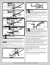
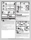
IF YOU HAVE A COUPLER ASSEMBLY:
Slide the center bearing into the center bracket. Align the stationary spring cone with the
holes in the center bearing bracket. Secure the torsion spring to the center bracket with (2)
3/8”-16 x 1-1/2” hex head bolts and (2) 3/8”-16 nuts. Repeat the same process for the
other center bearing bracket.
At the middle of the two center bearing brackets, re-assemble the coupler assembly by
loosely fastening the coupler halves together using the (3) 3/8”-16 x 1-3/4” hex head screws
and the (3) 3/8”-16 nylon hex lock nuts, as shown.
NOTE: Ensure both torsion keyed shafts have equal amounts of the shafts extending from
each end bearing brackets.
Typical center
bracket bushing
Stationary
spring cone
Typical center bracket
Torsion
spring
Stationary
spring cone
Torsion spring
Spring
warning tags
Typical center bracket
assembly
Stationary spring cone
(2) 3/8”-16 x 1-1/2”
Hex head bolts
(2) 3/8”-16 Nuts
Torsion
spring
Torsion
spring
Coupler halves
Coupler
assembly
(3) 3/8” - 16 x 1-3/4”
hex head screws and
(3) 3/8” - 16 Hex nuts
Stationary
spring cone
Torsion
spring
(2) 3/8”-16 x 1-1/2”
Hex head bolts and (2)
3/8”-16 Hex nuts
Torsion
spring
Center bracket
Center
bracket
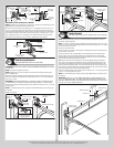
Counterbalance Lift Cables
Tools: Step Ladder, Locking Pliers, 3/8” Wrench
21
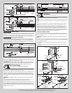
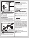
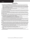
Starting on the left hand side, thread the counterbalance lift cable up and around the front
side of the left hand cable drum.
IMPORTANT: VERIFY THAT THERE ARE NO COUNTERBALANCE LIFT CABLE OBSTRUCTIONS.
Hook the counterbalance lift cable into the left hand cable drum. Slide the left hand cable
drum up against the left hand end bearing bracket. Counterbalance lift cable should
terminate at the 3 o’clock position. Tighten the (2) set screws in the drum to 14-15 ft. lbs. of
torque (once set screws contact the shaft, tighten screws one full turn).
NOTE: If you have torsion keyed shaft(s), insert (1) key into the slot of both the cable drum
and the slot in the torsion keyed shaft, as shown.
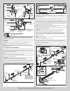
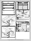
Rotate the left hand drum and torsion shaft until counterbalance lift cable is taut. Now attach
locking pliers to the torsion shaft and brace locking pliers up against jamb to keep counter-
balance lift cable taut.
Repeat for right hand side.
IMPORTANT: INSPECT EACH COUNTERBALANCE LIFT CABLES MAKING SURE THEY ARE
SEATED PROPERLY ONTO THE CABLE DRUMS AND THAT BOTH COUNTERBALANCE LIFT
CABLES HAVE EQUAL TENSION.
Left cable drum
Counterbalance cable hooked in cable drum
Left cable drum
Counterbalance lift cable
Locking pliers
Set screws
Jamb
Left end
bearing bracket
Torsion keyed
shaft
Key
Securing Door for Spring Winding(s)
Tools: Vice Clamps
22
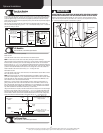
With the door in the fully closed position, place vice clamps onto both vertical tracks just
above the third track roller. This is to prevent the garage door from rising while winding
springs.
WARNING WARNING
FAILURE TO PLACE VICE CLAMPS ONTO VERTICAL TRACK CAN ALLOW
DOOR TO RAISE AND CAUSE SEVERE OR FATAL INJURY.
14