


Please Do Not Return This Product To The Store. Contact your local Wayne-Dalton dealer. To find your local Wayne-Dalton dealer,
refer to your local yellow pages business listings or go to the Find a Dealer section online at www.Wayne-Dalton.com
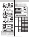
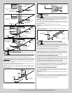
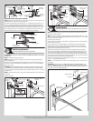
Typical top
fixture slide
Horizontal
track
Typical top
fixture slide
Stem track
roller
(1)1/4”-20 x 9/16”
Track bolt
Top
section
Top
section
(1) 1/4”-20
Flange hex
nut
5/16”-18
Flange hex
nut(s)
(2) 1/4”-20
Flange hex
nut(s)
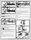
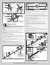
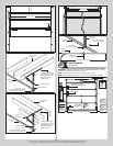
REVERSING THE TOP FIXTURE SLIDE, IF NEEDED:
NOTE: Depending on your application, you may have to reverse the top fixture slide for more
adjustability, prior to securing it to the top fixture base.
Remove the top fixture slide by removing the (2) 1/4”-20 flanged hex nuts and the (2) 1/4”-
20 x 5/8” carriage bolts. Remove the track roller from the top fixture slide and flip the top
fixture slide in the opposite direction. Re-insert the track roller back into the top fixture slide
and loosely fasten the top fixture slide to the top fixture base by re-using the (2) 1/4”-20 x
5/8” carriage bolts and (2) 1/4”-20 flange hex nuts. Repeat same process for other side.
Now follow the instructions at the top of this step “Adjusting top fixture slide(s)”.
Flip top fixture
slide
(2) 1/4”-20
Flange hex nuts
Top fixture
slide
(2) 1/4”-20 x 1/2”
Carriage bolts
Top fixture base
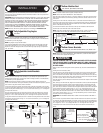
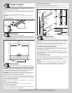
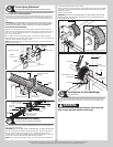
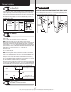
End Bearing Brackets
Tools: Step ladder, Power drill, 7/16” Socket driver
17
IMPORTANT: RIGHT AND LEFT HAND IS ALWAYS DETERMINED FROM INSIDE THE BUILDING
LOOKING OUT.
NOTE: End brackets are right and left hand.
NOTE: Depending on your door, you might have to break the end bearing brackets apart,
prior to installing them.
Attach the left hand end bearing bracket through either the end bearing bracket’s upper or
lower slots to the left hand horizontal track angle using (2) 3/8”-16 x 3/4” truss head bolts
and (2) 3/8”-16 nuts.
IMPORTANT: THE END BEARING BRACKET’S LOWER SLOTS ARE USED ON DOORS WITH
12” RADIUS TRACK; THE UPPER SLOTS ARE USED ON DOORS WITH 15” RADIUS TRACK.
Secure the top of the end bearing bracket to the jamb with the number of 5/16” x 1-5/8” lag
screw(s) shown.
NOTE: It is recommended that 5/16” lag screws are pilot drilled using a 3/16” drill bit, prior
to fastening.
Repeat for other side.
(2) 3/8”-16
Hex nuts
(2) 3/8”-16 x 3/4”
Truss head bolts
Left end bracket
Upper slots
Lower slots
Horizontal track angle
(1) 5/16” x 1-5/8”
Lag screw
Bend back and fourth to
seperate the (2) end
bearing brackets
(2) 3/8”-16
Hex nuts
(2) 3/8”-16 x 3/4”
Truss head bolts
Left end
bracket
Upper
slot
Lower slots
Horizontal
track angle
(3) 5/16” x 1-5/8”
Lag screws
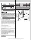
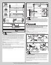
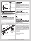
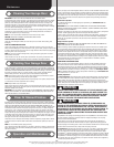
Center Bracket
Tools: Step ladder, Power drill, 7/16” Socket driver, 1/4” Torx bit, Level,
18
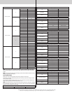
NOTE: Refer to the Package Contents and or Parts Breakdown to determine if your door
came with a coupler assembly.
NOTE: If your door came with a coupler assembly, the mounting surface needs to be a mini-
mum of 17” wide. The two center bearing brackets will need to be spaced 12” to 14” apart at
the center of the door, as shown.
Locate the center of the door.
If your door did not come with a coupler: Mark a vertical pencil line on the mounting surface
above the door, at the center.
If your door did come with a coupler: Mark a vertical pencil line on the mounting surface
above the door, at the center. Split the difference up and position the (2) center bearing
brackets apart from each other. Mark two vertical pencil lines, one for each center bearing
bracket onto the mounting surface above the door.
Measure from the center of the bearing, in one of the end bearing brackets, downwards,
to the top the door. Using that measurement, measure that distance upwards from the top
of the door to the mounting surface and mark a horizontal pencil line which intersects the
vertical pencil line(s). Align the edge of the center bracket(s) with the vertical pencil line and
the center of the center bracket(s) with the horizontal pencil line; this is to ensure the torsion
shaft is level between the center and end bearing brackets.
Attach the center bracket(s) to the mounting surface, using (2) 5/16” x 1-5/8” lag screws and
(1) 5/16” x 2” tamper-resistant lag screw.
NOTE: It is recommended that 5/16” lag screws are pilot drilled using a 3/16” drill bit, prior
to fastening.
IMPORTANT: USE A 5/16” X 1-5/8” TAMPER-RESISTANT LAG SCREW INSTEAD OF THE
5/16” X 2” TAMPER-RESISTANT LAG SCREW IF MOUNTING SURFACE IS MOUNTED OVER
MASONRY. TAMPER-RESISTANT LAG SCREW MUST BE ATTACHED THROUGH THE BOTTOM
HOLE OR SLOT OF THE CENTER BRACKET(S).
Center bearing
bracket
Vertical line
Mounting surface
Horizontal line
Center of end
bearing bracket
Equal distance (top of door section to horizontal line)
12