


Please Do Not Return This Product To The Store. Contact your local Wayne-Dalton dealer. To find your local Wayne-Dalton dealer,
refer to your local yellow pages business listings or go to the Find a Dealer section online at www.Wayne-Dalton.com
(3) 1/4” - 14 x 1”
Lag screws
2” Long strut
Typical
section
shown.
Center hinge
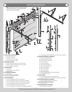
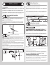
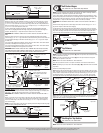
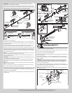
FOR 3” LONG STRUT APPLICATIONS:
Attach the upper slot of the graduated end hinge, (1) strut clip and the upper leg of strut to
the bottom section using (1) 1/4”-20 x 2-1/4” carriage bolt, (1) 1/4”–20 flange hex nut or
(1) 1/4”-20 x 1-3/8” bolt. Next secure the bottom leg of strut, the slot of the graduated end
hinge to the bottom section (1) 1/4”-20 x 2-1/4” carriage bolt, (1) 1/4”–20 flange hex nut or
(1) 1/4”-20 x 1-3/8” bolt. Repeat for other side.
For doors with double graduated end hinges, position the second graduated end hinge
next to the first (single) graduated end hinge. Using the second graduated end hinge as a
template, drill pilot holes, 1” deep into the bottom section with a 1/8” drill bit.
IMPORTANT: BE EXTREMELY CAREFUL NOT TO DRILL THRU THE SECTION. ONLY DRILL 1”
DEEP.
Attach the upper leg of strut to the upper slot of the graduated end hinge to the bottom
section using (1) 1/4”-14 x 1” lag screw. Next secure the bottom leg of strut to the lower slot
of the graduated end hinge to the bottom section using (1) 1/4”-14 x 1” lag screw. Repeat
for other side.
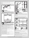
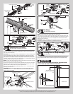
If you have single graduated end hinges, insert a short stem track roller / short stem tandem
track roller (if included) into the hinge tube on each side.
If you have double graduated end hinges, insert a long stem track roller / short stem tandem
track roller (if included) into the hinge tubes on each side.
IMPORTANT: WHEN PLACING TRACK ROLLERS / TANDEM TRACK ROLLER (IF INCLUDED)
INTO GRADUATED END HINGES NUMBER 2 AND HIGHER, THE TRACK ROLLER / TANDEM
TRACK ROLLER (IF INCLUDED) GOES INTO TUBE FURTHEST AWAY FROM SECTION.
(2) 1/4” - 20 x 2 1/4” Carriage bolts
and (2) 1/4” - 20 Flange hex nuts or
(2) 1/4” - 20 x 1-3/8” bolts
3” Long strut
(1) Strut
clip
Typical
section
shown.
Lower hinge
leaf(s)
Single graduated end hinge
with short stem track roller
Double graduated end hinge
with long stem track roller
Short
edge
Long edge
(2) 1/4” - 14 x 1”
Lag screws
(2) 1/4” - 20 x 2 1/4” Carriage bolts
and (2) 1/4” - 20 Flange hex nuts or
(2) 1/4” - 20 x 1-3/8” bolts
3” Long strut
(1) Strut
clip
Typical
section
shown.
Lower hinge
leaf(s)
Single graduated end hinge with
short stem tandem roller
Double graduated end hinge
with long stem tandem roller
Short
edge
Long edge
(2) 1/4” - 14 x 1”
Lag screws
Tandem
roller
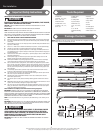
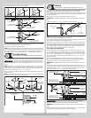
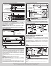
For Center Hinges, align the slots of the lower hinge leaf with the pre-drilled holes or at
each center stile at the top rail of bottom section. Using the center hinge as a template, drill
pilot holes, 1” deep into the bottom section with a 1/8” drill bit (if needed).
IMPORTANT: BE EXTREMELY CAREFUL NOT TO DRILL THRU THE SECTION. ONLY DRILL 1”
DEEP.
Attach (1) strut clip strut, top leg of strut to the lower slot of the center hinge to the bottom
section using (1) 1/4”-14 x 1” lag screws. Next secure the bottom leg of strut to the lower
slot of the center hinge to the bottom section using (1) 1/4”-14 x 1” lag screw. Repeat for
other center hinge(s).
NOTE: Ensure the short edge of the strut clip is pointing towards the hinge and the long edge
of the strut clip is pointing towards the strut.
(2) 1/4” - 14 x 1”
Lag screws
Strut clip
Center hinge
3” Long strut
Lower
hinge
leaf
(1) Strut clip
Short edge
Long edge
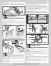
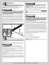
Half Center Hinges
Tools: Power drill, 7/16” Socket driver, Tape measure
7
NOTE: If you don’t have half center hinges, then skip this step. Refer to Package Contents /
Parts Breakdown, to determine if you have half center hinges.
Using a tape measure, position the half center hinges equally spaced in between the center
hinges and equally spaced in between the center hinges and the graduated end hinges. Posi-
tion the holes of the lower hinge leaf, as shown. Using the half center hinge as a template,
drill pilot holes, 1” deep into the bottom section with a 1/8” drill bit (if needed).
IMPORTANT: BE EXTREMELY CAREFUL NOT TO DRILL THRU THE SECTION. ONLY DRILL 1”
DEEP.
Attach the lower hinge leaf of the center hinge to the bottom section using (2) 1/4”-14 x 1”
lag screws. Repeat for other half center hinge(s).
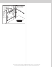
Set the bottom section aside and place the Intermediate I section face down on a couple of
sawhorses or flat clean/ smooth surface. Reference step Strutting and this step to attach the
long struts and hinges to the top rail of the section in the same manner. Repeat the same
process for the other Intermediate II section and the Intermediate III section (if applicable).
(2) 1/4” - 14 x 1” Lag screws
Long strut
Typical section
shown.
Equally spaced
Half
center
hinge
Lower hinge leaf
Center
hinge
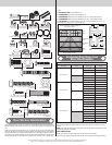
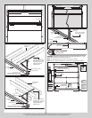
Top Fixtures
Tools: Power drill, 7/16” Socket driver
8
NOTE: If your door came with two top fixtures (A), then one top fixture and a short stem track
roller are required for each side.
NOTE: If your door came with four top fixtures (B), then two top fixtures and a long stem
track roller are required for each side.
NOTE: Refer to Door Section Identification / Parts Breakdown.
Place the top section face down on a couple of sawhorses or flat clean/ smooth surface.
NOTE: Depending on your door, refer to illustrations (A) or (B) to determine how to install the
top fixtures.
Follow the corresponding steps below:
(A): Starting on the left hand side, align the edge of the top fixture parallel to the top section
edge. Using the top fixture as a template, mark and pre-drill (3) 9/32” diameter holes through
the top section. Loosely attach the top fixture to the top section using (2) 1/4”-20 x 2-1/4”
carriage bolts and (2) 1/4-20 flange hex nuts or (2) 1/4”-20 x 1-3/8” bolts. Insert a short
stem track roller into the top fixture slide. Repeat the same process for the right hand side.
(C) Left hand
top fixture
(2) 1/4” - 20 x 1-3/8”
bolts
(C) Left hand
top fixture
Short stem
track roller
Short stem
track roller
(2) 1/4” - 20
Flange hex nuts
(2) 1/4” - 20 x 2 1/4”
Carriage bolts
Top section
Top section
Factory
installed
threads
(B): Position the second top fixture next to the first installed top fixture and loosely attach it
with (2) 1/4 – 14 x 1” lag screws. Insert a long stem track roller into the top fixture slides.
Repeat the same process for the right hand side.
(2) Top
fixtures
Long stem
track roller
(2) 1/4” - 14 x 1”
Lag screws
(D) Left hand
top fixture
Top section
Strutting For Top Section
Tools: Power drill, 7/16” Socket driver
9
NOTE: Refer to Door Section Identification / Parts Breakdown.
9