


Please Do Not Return This Product To The Store. Contact your local Wayne-Dalton dealer. To find your local Wayne-Dalton dealer,
refer to your local yellow pages business listings or go to the Find a Dealer section online at www.Wayne-Dalton.com
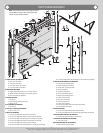
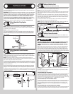
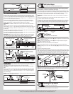
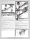
with the left bottom edge of the bottom section. Attach the bottom corner bracket to the bot-
tom section using (3) 1/4”-20 x 1-3/8” bolts, as shown.
Bottom section, with no
holes.
Bottom section, with factory
installed threads.
Bottom section, with pre-drilled
holes.
Typical left hand
bottom corner bracket
Bottom
section
(3) 1/4” - 20 x 2 1/4”
Carriage bolts
(3) 1/4” - 20
Flange hex nuts
(1) 1/4” - 10 x 1” Tamper
resistant lag screw
Typical left hand
bottom corner bracket
Bottom
section
(1) 1/4” - 10 x 1” Tamper
resistant lag screw
(3) 1/4” - 20 x 1 3/8”
Bolts
Next, secure the bottom corner bracket to the bottom section using (1) 1/4”-14 x 1” tamper
proof screw to the left hand bottom corner bracket, as shown.
Repeat the same process for the right hand side.
NOTE: All doors are provided with the tamper resistant fastener for the bottom corner brack-
ets. However, the professional installer is most likely to have the proper tool to install this fas-
tener. If the homeowner does not have the proper tool to install the tamper resistant fastener,
use a regular 1/4”-20 x 2-1/4” carriage bolt and a 1/4”–20 flange hex nut in its place.
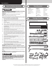
Track Roller Carriers
Tools: Power Drill, 9/32” Drill Bit, Socket Driver 7/16”, Wrench 7/16”
5
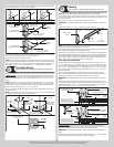
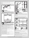
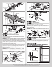
Starting on left hand side of the bottom section, attach the track roller carrier with the stamp
“STD” facing UP to the bottom corner bracket by aligning the four holes of the track roller
carrier with the four holes in the bottom corner bracket. Secure the track roller carrier to the
bottom corner bracket with (4) 1/4”-20 x 7/8” self drilling screws or (4) 1/4”-14 x 1” lag
screws.
NOTE: Depending on your door, some track roller carriers will use 1/4”-14 x 1” lag screws
instead of the 1/4”-20 x 7/8” self drilling screws to secure in place. If this is the case, mark
and pre-drill (4) 1/8” diameter holes and secure the track roller carrier to the bottom corner
bracket and bottom section using (4) 1/4”-14 x 1” lag screws.
Insert a short stem track roller and spacer into the inner holes. Repeat the same process for
the right hand side.
NOTE: The track roller carrier’s inner holes are used on doors with 2” track applications; the
outer holes are used on doors with 3” track applications.
Short stem
track roller
Spacer
(4) 1/4” - 20 x 7/8”
Self drilling screws
Bottom corner
bracket track
roller carrier
Bottom corner
bracket
“STD”
facing UP
(4) 1/4” - 20 x 7/8”
Self drilling screws
Bottom corner
bracket track
roller carrier
Short
stem
track
roller
Spacer
Bottom corner
bracket
Side view of track roller
carrier(s)
Inner holes
(2” Track)
Outer holes
(3” Track)
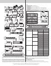
Strutting
Tools: Power Drill, 1/8”/9/32” Drill Bit, Socket Driver 7/16”, Tape
6
NOTE: Refer to Graduated End Hinge and Strut Identification / Parts Breakdown.
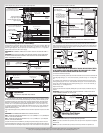
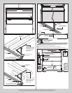
Lay the short strut onto the bottom rail of the bottom section. Position the bottom of the strut
3/4” up from the bottom edge of the bottom section. Center the short strut from side to side
on the section surface.
Drill pilot holes, 1” deep into the bottom section with a 1/8” drill bit.
IMPORTANT: BE EXTREMELY CAREFUL NOT TO DRILL THRU THE SECTION. ONLY DRILL 1”
DEEP.
Attach the strut using (1) 1/4”-14 x 1” lag screw at each pre-drilled hole.
1/4” - 14 x 1”
Lag screws
Short
strut
3/4”
Bottom corner
bracket
Bottom
section
NOTE: Refer to the Door Section Identification, Graduated End Hinge and Strut Identification,
to determine the appropriate hinges/struts for your section.
Using the appropriate graduated end hinges for the ends and depending on the width of your
door, enough center hinge(s) for each pre-drilled location(s).
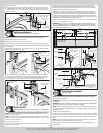
Starting at the upper left hand corner of the bottom section. Position the lower hinge leaf of
the appropriate graduated end hinge onto the upper corner of the bottom section. Align the
slots of the lower hinge leaf with the pre-drilled holes or the factory installed threads in the
bottom section. Next, lay a long strut over the lower hinge leaf and over the top rail of the
bottom section. Center the long strut from side to side, as shown.
FOR 2” LONG STRUT APPLICATIONS:
Attach the upper slot of the graduated end hinge to the bottom section using (1) 1/4”-20
x 2-1/4” carriage bolt, (1) 1/4”–20 flange hex nut or (1) 1/4”-20 x 1-3/8” bolt. Attach the
lower slot of the graduated end hinge and the upper leg of strut to the bottom section using
(1) 1/4”-20 x 2-1/4” carriage bolt, (1) 1/4”–20 flange hex nut or (1) 1/4”-20 x 1-3/8” bolt.
Next secure the bottom leg of strut to the bottom section using (1) 1/4”-20 x 1-3/8” bolt.
Repeat for other side.
For doors with double graduated end hinges, position the second graduated end hinge
next to the first (single) graduated end hinge. Using the second graduated end hinge as a
template, drill pilot holes, 1” deep into the bottom section with a 1/8” drill bit.
IMPORTANT: BE EXTREMELY CAREFUL NOT TO DRILL THRU THE SECTION. ONLY DRILL 1”
DEEP.
Attach the upper slot of the graduated end hinge to the bottom section using (1) 1/4”-14 x
1” lag screw. Attach the upper leg of strut to the lower slot of the graduated end hinge to the
bottom section using (1) 1/4”-14 x 1” lag screw. Next secure the bottom leg of strut to the
bottom section using (1) 1/4”-14 x 1” lag screw. Repeat for other side.
2” Long strut
Typical
section
shown.
(4) 1/4” - 14 x 1”
Lag screws
(2) 1/4” - 20 x 2 1/4”
Carriage bolts and (2) 1/4”
- 20 Flange hex nuts or (2)
1/4” - 20 x 1-3/8” bolts
Single graduated end hinge with
short stem track roller
Double graduated end hinge with
long stem track roller
2” Long strut
Typical
section
shown.
(4) 1/4” - 14 x 1”
Lag screws
(2) 1/4” - 20 x 2 1/4”
Carriage bolts and (2) 1/4”
- 20 Flange hex nuts or (2)
1/4” - 20 x 1-3/8” bolts
Single graduated end hinge with
short stem tandem track roller
Double graduated end hinge with
long stem tandem track roller
Tandem
track roller
For Center Hinges, align the slots of the lower hinge leaf with the pre-drilled holes or at
each center stile at the top rail of bottom section. Using the center hinge as a template, drill
pilot holes, 1” deep into the bottom section with a 1/8” drill bit (if needed).
IMPORTANT: BE EXTREMELY CAREFUL NOT TO DRILL THRU THE SECTION. ONLY DRILL 1”
DEEP.
Attach the strut and center hinge to the bottom section using (2) 1/4”-14 x 1” lag screws at
each pre-drilled hole. Repeat same process for other center hinge(s).
8