


Please Do Not Return This Product To The Store. Contact your local Wayne-Dalton dealer. To find your local Wayne-Dalton dealer,
refer to your local yellow pages business listings or go to the Find a Dealer section online at www.Wayne-Dalton.com
adjusted for each side.
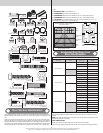
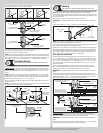
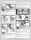
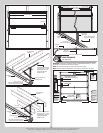
Starting on the left hand side, vertically align the top section of the door with the lower sec-
tions. Maintaining the top fixture(s) position, tighten the 1/4”-20 flange hex nuts or 1/4”-20
x 1-3/8” bolts and or 1/4”-14 x 1” lag screws to secure the top fixture(s) to the top section.
Repeat for other side
Left hand top fixture(s)
Track roller
(2) 1/4” - 20 Flange hex nuts or
(2) 1/4” - 20 x 1-3/8” bolts
Horizontal
tracks
Top section
Top
rail
Flag angle
(2) 1/4” - 14 x 1”
Lag screws
End Bearing Brackets
Tools: Step ladder, Power drill, 7/16” Socket driver
16
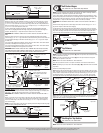
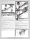
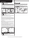
NOTE: Right and left hand is always determined from inside the garage looking out.
End bearing brackets are right and left hand.
Identify the end bearing brackets supplied with your door.
Align the bottom edge of left end bearing bracket with the top edge of the flag angle. Main-
taining this alignment, also align the right edge of the end bearing bracket with the right edge
of the flag angle.
Secure the end bearing bracket to the jamb using (3) 5/16” x 1-5/8” lag screws, as shown.
Repeat same process for the other side.
Left end bearing
bracket
Top
section
(3) 5/16” x 1-5/8”
Lag screws
Top
section
Top edge
of flag
angle
Bottom
edge
Left end bearing
bracket
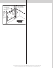
Position the left hand end bearing bracket up against the jamb and the horizontal track, as
shown. Fasten the left hand end bearing bracket to the horizontal track with (1) 3/8”-16 x
3/4” truss head bolt and (1) 3/8”-16 nut. Secure the left hand end bearing bracket to the
jamb using (3) 5/16” x 1-5/8” lag screws. Repeat same process for the other side.
(1) 3/8”-16
Hex nut
(1) 3/8”-16 x 3/4”
Truss head bolt
Upper
slot
Horizontal
track
(3) 5/16” x 1-5/8”
Lag screws
Left end bearing
bracket
Left end bearing bracket
Horizontal
track
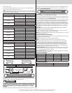
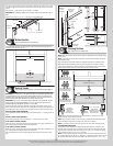
Center Bracket
Tools: Step ladder, Power drill, 7/16” Socket driver, 1/4” Torx bit, Level,
17
NOTE: Refer to the Package Contents and or Parts Breakdown to determine if your door
came with a coupler assembly.
NOTE: If your door came with a coupler assembly, the mounting surface needs to be a mini-
mum of 17” wide. The (2) center bearing brackets will need to be spaced 12” to 14” apart, at
the center of the door, as shown.
Locate the center of the door.
If your door did not come with a coupler: Mark a vertical pencil line on the mounting surface
above the door, at the center.
If your door did come with a coupler: Mark a vertical pencil line on the mounting surface
above the door, at the center. Split the difference up and position the (2) center bearing
brackets apart from each other. Mark two vertical pencil lines, one for each center bearing
bracket onto the mounting surface above the door.
Measure from the center of the bearing, in one of the end bearing brackets, downwards,
to the top the door. Using that measurement, measure that distance upwards from the top
of the door to the mounting surface and mark a horizontal pencil line which intersects the
vertical pencil line(s). Align the edge of the center bracket(s) with the vertical pencil line and
the center of the center bracket(s) with the horizontal pencil line; this is to ensure the torsion
shaft is level between the center and end bearing brackets.
Attach the center bracket(s) to the mounting surface, using (2) 5/16” x 1-5/8” lag screws and
(1) 5/16” x 2” tamper-resistant lag screw.
IMPORTANT: USE A 5/16” X 1-5/8” TAMPER-RESISTANT LAG SCREW INSTEAD OF THE
5/16” X 2” TAMPER-RESISTANT LAG SCREW IF MOUNTING SURFACE IS MOUNTED OVER
MASONRY. TAMPER-RESISTANT LAG SCREW MUST BE ATTACHED THROUGH THE BOTTOM
HOLE OF THE CENTER BRACKET(S).
Typical
center
bracket
Vertical
line
Mounting
surface
Horizontal
line
Center of typical
end bearing bracket
Center of typical
end bearing bracket
Equal distance from
top of door section
to horizontal line
Center bracket
bushing assembly
(1) 5/16” X 2” or (1) 5/16” x 1-5/8” Tamper-resistant lag screw
(2) 5/16” x 1-5/8”
Lag screws
Vertical
line
Mounting
surface
Horizontal
line
Vertical
line
Mounting
surface
Horizontal
line
Center
bearing
bracket
assembly
(2) 5/16” x 1-5/8”
Lag screws
(1) 5/16” X 2” or (1) 5/16”
x 1-5/8” Tamper-resistant
lag screw
Vertical
line
Mounting surface
(17” Minimum)
Horizontal
line
(2) 5/16” x 1-5/8”
Lag screws
Vertical line
(2) 5/16” x 1-5/8”
Lag screws
† (2) Center bearing
brackets spaced 6” to 7”
apart from the center of
the door.
Center
of
door
†
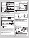
Torsion Spring Assembly
Tools: Step Ladder
18
NOTE: Refer to the Package Contents and or Parts Breakdown to determine if your door
came with a coupler assembly.
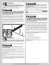
IMPORTANT: RIGHT AND LEFT HAND IS ALWAYS DETERMINED FROM INSIDE THE BUILDING
LOOKING OUT.
IMPORTANT: ON SINGLE SPRING APPLICATIONS, ONLY A RIGHT HAND WOUND (RED WIND-
ING CONE), WHICH GOES ON THE RIGHT HAND SIDE IS REQUIRED.
NOTE: Identify the torsion springs provided as either right hand wound (red winding cone),
which goes on the RIGHT HAND SIDE or left hand wound (black winding cone), which goes on
the LEFT HAND SIDE.
For Doors without Coupler Assembly:
Facing the inside of the door lay the torsion shaft on the floor. Lay the torsion spring with the
black winding cone and the red cable drum at the left end of the torsion shaft. Lay the torsion
spring with the red winding cone and the black cable drum at the right end of the torsion
shaft.
NOTE: The set screws used on all torsion winding cones and cable drums are now colored
red. DO NOT identify right and left hand by the set screw color.
Slide the center bracket bushing or center bearing onto the torsion shaft followed by the
torsion springs.
12