


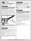

Please Do Not Return This Product To The Store. Contact your local Wayne-Dalton dealer. To find your local Wayne-Dalton dealer,
refer to your local yellow pages business listings or go to the Find a Dealer section online at www.Wayne-Dalton.com
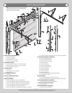
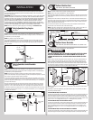
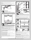
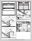
Lay a short strut onto the top rail of the top section. Position the top of the strut 3/4” down
from the top edge of the top section. Center the short strut from side to side on the section
surface.
Drill pilot holes, 1” deep into the top section with a 1/8” drill bit.
IMPORTANT: BE EXTREMELY CAREFUL NOT TO DRILL THRU THE SECTION. ONLY DRILL 1”
DEEP.
Attach the strut using (1) 1/4”-14 x 1” lag screw at each predrilled hole.
Top section
Typical top
fixture
1/4” - 14 x 1”
Lag screws
Short strut
3/4”
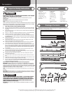
Bottom Section
Tools: Level, Wooden shims (if necessary)
10
Center the bottom section in the door opening. Level the section using wooden shims (if
necessary) under the bottom section.
Weather seal
Level
Bottom section
Wooden shims
(If necessary)
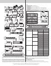
Vertical Tracks
Tools: Power Drill, 3/16” Drill bit, 7/16” Socket driver, Tape measure,
11
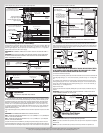
IMPORTANT: IF YOUR DOOR IS TO BE INSTALLED PRIOR TO A FINISHING CONSTRUCTION
OF THE BUILDING’S FLOOR, THE VERTICAL TRACKS AND THE DOOR BOTTOM SECTION
ASSEMBLY SHOULD BE INSTALLED SUCH THAT WHEN THE FLOOR IS CONSTRUCTED, NO
DOOR OR TRACK PARTS ARE TRAPPED IN THE FLOOR CONSTRUCTION.
IMPORTANT: THE TOPS OF THE VERTICAL TRACKS MUST BE LEVEL FROM SIDE TO SIDE.
IF THE BOTTOM SECTION WAS SHIMMED TO LEVEL IT, THE VERTICAL TRACK ON THE
SHIMMED SIDE MUST BE RAISED THE HEIGHT OF THE SHIM.
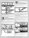
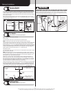
Position the left hand vertical track assembly / wall angle track assembly over the track
rollers of the bottom section. Make sure the counterbalance lift cable is located between the
track rollers and the door jamb. Drill 3/16” pilot holes into the door jamb for the lag screws.
FOR FLAG ANGLE TRACK ASSEMBLIES:
Loosely fasten jamb brackets and flag angle to the jamb using 5/16” x 1-5/8” lag screws, as
shown.
FOR WALL ANGLE TRACK ASSEMBLY:
Loosely fasten wall angle to the jamb using 5/16” x 1-5/8” lag screws, as shown.
IF YOU HAVE 2” VERTICAL TRACKS:
Tighten lag screws, securing the bottom jamb bracket/bottom slot to jamb, maintain 3/8” to
5/8” spacing, between the bottom section and vertical track.
IF YOU HAVE 3” VERTICAL TRACKS:
Tighten lag screws, securing the bottom jamb bracket/bottom slot to jamb, maintain 1/2” to
3/4” spacing, between the bottom section and vertical track.
Hang counterbalance lift cable over flag angle/wall angle. Repeat same process for other
side.
2” Vertical track
spacing (3/8” to 5/8”)
3” Vertical track
spacing (1/2” to 3/4”)
Bottom
section
Floor
Track roller
Wallangle
track
assembly
Jamb
bracket
Riveted track
flag angle
shown
Riveted
flag angle
5/16” x 1-5/8”
Lag screws
Bottom
section
Track
rollers
Vertical track
assembly
Flag
angle
Lag
screw
locations
Fully Adjustable
flag angle
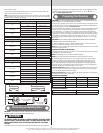
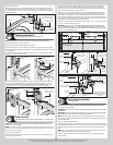
Stacking Sections
Tools: Power drill,7/16” Socket driver
12
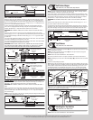
NOTE: Make sure graduated end and center hinges are flipped down, when stacking another
section on top.
NOTE: Larger doors will use long stem track rollers / long stem tandem rollers with double
graduated end hinges.
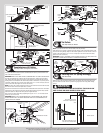
Place track rollers and or tandem rollers into graduated end hinges of remaining sections.
With assistance, lift intermediate I (second) section and guide the track rollers / tandem
rollers into the vertical tracks. Lower section until it is seated against bottom section. Keep
sections aligned. Repeat same process for other sections, except top section.
Center
hinge(s)
Left single
graduated end
hinge with
typical short
stem track roller
Right single
graduated end hinge
with typical short
stem track roller
(2) 1/4”-20 x 2-1/4” Carriage bolts and (2) 1/4”-20 Flange hex nuts
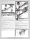
Intermediate I section
Bottom section
Vertical
tracks
Left double graduated
end hinge with typical
long stem track roller
Typical graduated end
hinge with typical long
stem tandem track roller
Right double graduated
end hinge with typical
long stem track roller
(2) 1/4”-14 x 1” Lag screws
NOTE: Refer to Graduated End Hinge And Strut Identification, to determine if your doors
requires strutting, prior to attaching sections.
NOTE: Follow the typical practice, as shown in Steps Strutting and Step Half Center Hinges
prior to installing the long struts and hinges to the lower rail of section(s).
NOTE: If no strutting is require on the lower rail of section, then follow instructions below.
FOR GRADUATED END HINGES:
Starting with the outer graduated end hinges, flip the upper hinge leaf up and use it as a
template. Mark and pre-drill (2) 9/32” diameter holes through the section. Attach the upper
hinge leaf, strut (if required) to the section using (2) 1/4”-20 x 2-1/4” carriage bolts and (2)
1/4”–20 flange hex nuts or (2) 1/4”-20 x 1-3/8” bolts.
NOTE: If you have double graduated end hinges, flip the inner upper hinge leaf up and use it
as a template. Mark and pre-drill (2) 1/8” pilot holes, 1” deep into the section with a 1/8” drill
bit. Attach the upper hinge leaf, strut (if required) to the section using (2) 1/4”-14 x 1” lag
10