


Please Do Not Return This Product To The Store. Contact your local Wayne-Dalton dealer. To find your local Wayne-Dalton dealer,
refer to your local yellow pages business listings or go to the Find a Dealer section online at www.Wayne-Dalton.com
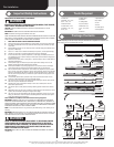
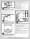
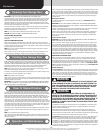
Horizontal tracks
Door edges
3/4” To 7/8”
3/4” To 7/8”
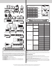
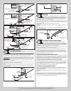
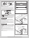
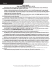
Attaching Front Cable Lift Sheaves
Tools: 3/8” Wrench, Tape Measure
18
Measure the front cable lift sheaves to determine if they are 3 or 4 inches. Starting on the left
hand side and using (1) 3/8”-16 hex nut, attach the front cable lift sheave into the appropri-
ate hole, as shown).
IF YOU HAVE 3” FRONT CABLE LIFT SHEAVES AND A 12” RADIUS HORIZONTAL
TRACK:
Secure the front cable lift sheave to the 13/32” hole near the top of the flag angle using (1)
3/8”-16 hex nut, as shown.
IF YOU HAVE 3” OR 4” FRONT CABLE LIFT SHEAVES AND A 15” RADIUS HORIZONTAL
TRACK:
Bolt the front cable lift sheave to the first 13/32” hole in the horizontal track angle, using (1)
3/8”-16 hex nut, as shown.
Repeat the same process for right hand side.
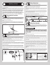
Remove the locking pliers from the vertical tracks. With assistance, raise the door slowly into
the open position making sure the door travels smoothly through the tracks. Clamp locking
pliers to the back leg of both horizontal tracks, below the bottom track rollers to keep the
door from lowering.
Flag angle
Front cable lift sheave
3/8”-16
Hex nut
Horizontal
track angle
15” Radius horizontal track
with 3” or 4” front cable lift
sheave hole location
12” Radius horizontal
track with 3” front cable
lift sheave hole location
Horizontal track
3” Or 4”
Front cable
lift sheave
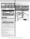
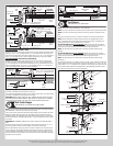
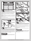
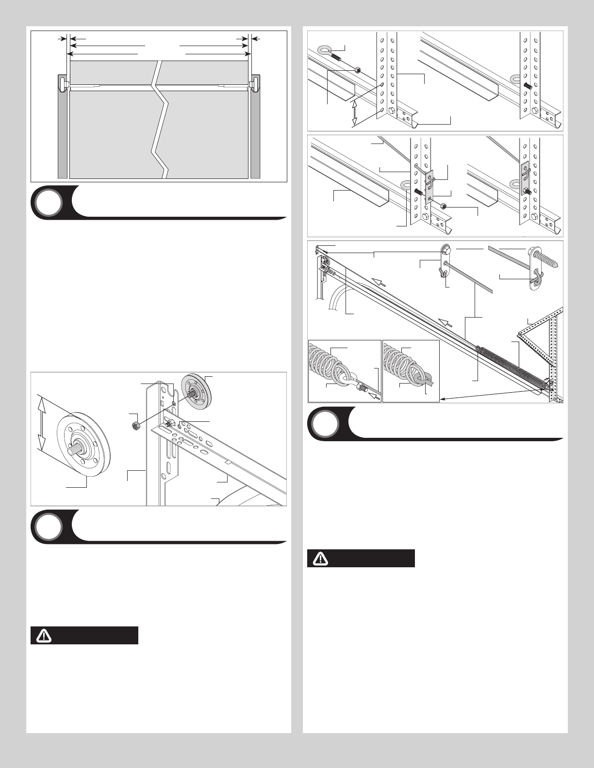
Attaching Extension Springs
Tools: 3/8” Wrench
19
Position (1) 5/16”-18 x 3-3/4” eye bolt and (1) 5/16”-18 hex nut in the rear back hang, 6” to
8” above the horizontal track, as shown. Feed the snubber cable through the rear back hang
and tie the special knot around the “room side” of the 3 hole clip, as shown. Secure the eye
bolt and 3 hole clip to the rear back hang with (1) 5/16” - 18 hex nut. Hook one end of the
extension spring onto the eye bolt. Feed the snubber cable through the rear extension spring
loop and center of the extension spring then front spring loop, pull the snubber cable taut and
tie the special knot around the “jamb side” of the 3 hole clip. Attach the “jamb side” 3 hole
clip to the jamb near the flag angle with (1) 5/16” x 1-5/8” lag bolt.
NOTE: Snubber cables must be taut.
WARNING WARNING
FAILURE TO INSTALL SNUBBER CABLES CAN RESULT IN SEVERE OR FATAL INJURY
IN CASE OF SPRING BREAKAGE.
6”-8”
(1) 5/16”-18
Hex nut
(1) 5/16”-18 x 3-3/4”
Eye bolt
Horizontal
track
Rear back hang
(Perforated angle)
(1) 5/16”-18
Hex nut
(1) 5/16”-18 x 3-3/4”
Eye bolt
Spring safety
cable
Special
knot
3 Hole clip
Horizontal track
Rear back
hang
Rear back
hang
Extension
spring
Spring
safety
cable
3 Hole clip
Extension
spring loop
(1) 5/16” x 1-5/8”
Lag screw
Special
knot
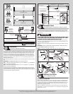
Back view
Front view
3 Hole
clip
Special
knot
Spring
safety
cable
Extension
spring
Extension
spring loop
Extension
spring
Extension
spring loop
Eye
bolt
Spring
safety
cable
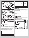
Attaching Spring Sheaves
Tools: 3/8” Wrench
20
Hook the sheave fork through the front loop of the extension spring and attach the sheave
fork to the rear cable lift sheave using (1) 3/8”-16 x 1-1/4” hex head bolt and (1) 3/8”-16
hex nut.
Thread the counterbalance lift cable over the front cable lift sheave and around the rear
cable lift sheave and tie the special knot around the “horizontal angle” using a 3 hole clip, as
shown.
Insert one end of the large “S” hook into the “horizontal angle” with the 3 hole clip and the
other end into the second slot of the horizontal angle, as shown.
Repeat for the other side.
IMPORTANT: CLOSE “S” HOOKS AND EYE BOLTS TO PREVENT SPRINGS FROM COMING
LOOSE.
WARNING WARNING
FAILURE TO CLOSE “S” HOOKS AND EYE BOLTS CAN RESULT IN SEVER OR
FATAL INJURY IF SPRINGS COME LOOSE.
NOTE: Some larger doors feature 2 pairs of extension springs. A snubber cable must be
installed through each spring.
12