


Please Do Not Return This Product To The Store. Contact your local Wayne-Dalton dealer. To find your local Wayne-Dalton dealer,
refer to your local yellow pages business listings or go to the Find a Dealer section online at www.Wayne-Dalton.com
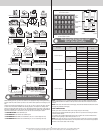
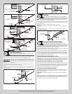
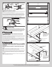
Typical top
fixture slide
Horizontal
track
Typical top
fixture slide
Stem track
roller
(1)1/4”-20 x 9/16”
Track bolt
Top
section
Top
section
(1) 1/4”-20
Flange hex
nut
5/16”-18
Flange hex
nut(s)
(2) 1/4”-20
Flange hex
nut(s)
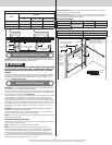
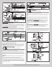
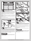
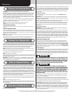
REVERSING THE TOP FIXTURE SLIDE, IF NEEDED:
NOTE: Depending on your application, you may have to reverse the top fixture slide for more
adjustability, prior to securing it to the top fixture base.
Remove the top fixture slide by removing the (2) 1/4”-20 flanged hex nuts and the (2) 1/4”-
20 x 5/8” carriage bolts. Remove the track roller from the top fixture slide and flip the top
fixture slide in the opposite direction. Re-insert the track roller back into the top fixture slide
and loosely fasten the top fixture slide to the top fixture base by re-using the (2) 1/4”-20 x
5/8” carriage bolts and (2) 1/4”-20 flange hex nuts. Repeat same process for other side.
Now follow the instructions at the top of this step “Adjusting top fixture slide(s)”.
Flip top fixture
slide
(2) 1/4”-20
Flange hex nuts
Top fixture
slide
(2) 1/4”-20 x 1/2”
Carriage bolts
Top fixture base
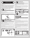
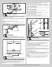
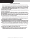
Rear Back Hangs
Tools: Ratchet wrench, Socket: 1/2” 5/8”, Wrench: 1/2” 5/8”, (2) Vice
17
Raise the door until the top section and half of the next section are in a horizontal position.
Do not raise door any further since rear of horizontal tracks are not yet supported.
WARNING WARNING
RAISING DOOR FURTHER CAN RESULT IN DOOR FALLING AND CAUSE
SEVERE OR FATAL INJURY.
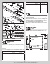
Clamp a pair of vice clamps onto the vertical tracks just above the second roller on one side,
and just below the second track roller on the other side. This will prevent the door from rais-
ing or lowering while installing the rear back hangs.
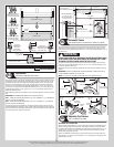
Using perforated angle (may not be supplied), (2) 5/16” x 1-5/8” hex head lag screws and
(3) 5/16” bolts with nuts (may not be supplied), fabricate rear back hangs for the horizontal
tracks. Attach horizontal tracks to the rear back hangs with 5/16”-18 x 1 hex bolts and nuts
(may not be supplied). Horizontal tracks must be level and parallel with door within 3/4” to
7/8” maximum of door edge.
WARNING WARNING
KEEP HORIZONTAL TRACK PARALLEL AND WITHIN 3/4” TO 7/8” MAXIMUM
OF DOOR EDGE, OTHERWISE DOOR COULD FALL, RESULTING IN SEVERE OR
FATAL INJURY.
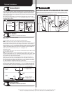
IMPORTANT: DO NOT SUPPORT THE WEIGHT OF THE DOOR ON ANY PART OF THE HORI-
ZONTAL TRACK HANGER THAT CANTILEVERS 4” OR MORE BEYOND A SOUND FRAMING
MEMBER.
NOTE: If rear back hangs are to be installed over drywall, use (2) 5/16” x 2” hex head lag
screws and make sure lag screws engage into solid structural lumber.
NOTE: 26” angle must be attached to sound framing members and nails should not be used.
Now, permanently attach the weatherstrips on both door jambs and header. The weather-
strips were temporarily attached in Preparing the Opening, in the pre-installation section of
this manual.
NOTE: When permanently attaching the weatherstrips to the jambs, avoid pushing the weath-
erstrips too tightly against the face of door.
Vice clamp
Horizontal tracks
2nd Track roller
Vice clamp
5/16”-18 x 1-1/4”
Hex bolt must extend into the
track to serve as a roller stop
Perforated angle
Sound framing
members
Horizontal
track
(3) 5/16” Bolts and nuts
Perforated angle bolted
using (2) 5/16” x 1-5/8”
hex head lag screws to
ceiling member and
parallel to door
Perforated angle
Sound framing
members
Horizontal
track
(3) 5/16”
Bolts and nuts
Perforated angle bolted
using (2) 5/16” x 1-5/8”
hex head lag screws to
ceiling member and
parallel to door
5/16”-18 x 1-1/4”
Hex bolt must extend into the
track to serve as a roller stop
11