


107156-01E
For more information, visit www.desatech.com
For more information, visit www.desatech.com
8
INSTALLATION
Continued
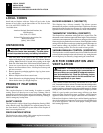
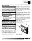
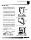
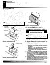
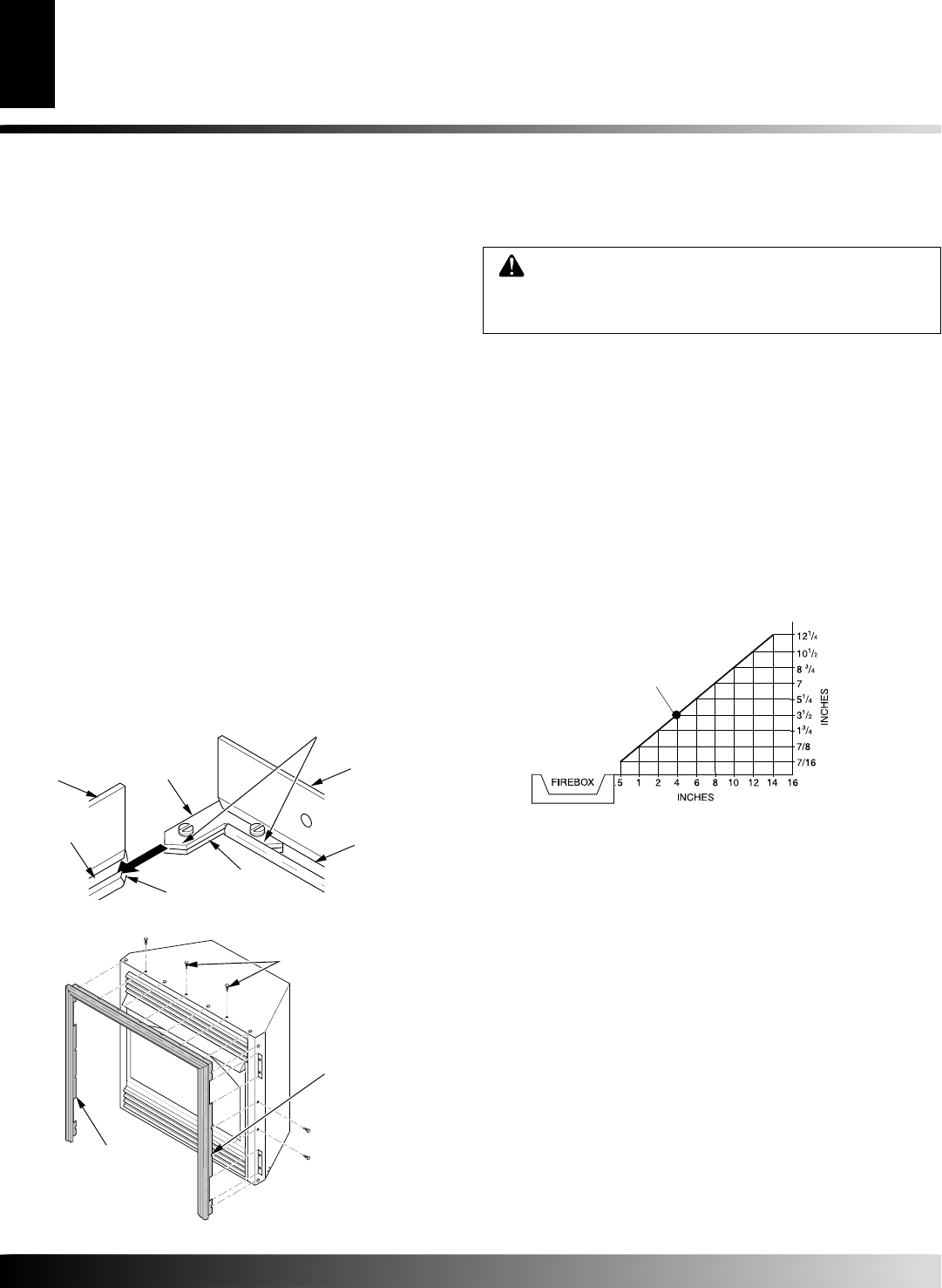
Figure 7 - Attaching Brass Trim to Fireplace
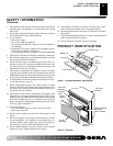
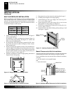
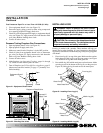
Figure 6 - Assembling Brass Trim
IMPORTANT:
If you are recessing the firebox in a wall, do not attach
brass trim at this time. See page 10 for built-in fireplace installation.
Note:
The instructions below show assembling and attaching brass
trim to fireplace.
1. Remove packaging from three pieces of brass trim.
2. Locate four brass screws, two adjusting plates with set screws,
and two shims in the hardware packet.
3. Align shim under adjusting plate as shown in Figure 6.
4. Slide one end of adjusting plate/shim in slot on mitered edge
of top brass trim (see Figure 6).
5. Slide other end of adjusting plate/shim in slot on mitered edge
of side brass trim (see Figure 6).
6. While firmly holding edges of brass trim together, tighten both
set screws on the adjusting plate with slotted screwdriver.
7. Repeat steps 1 through 6 for other side.
8. Tighten trim hanging screws (#10 x 6.25 shoulder) into holes
in cabinets. Place the assembled trim onto fireplace cabinet.
Align hanging notches on trim with hanging screws on side of
fireplace (see Figure 7). Push trim firmly into place, sliding
hanging notches over hanging screws.
ASSEMBLING AND ATTACHING OPTIONAL
BRASS TRIM
(Included with Mantel Accessory)
Side Brass
Trim
Top Brass
Trim
Slot
Mitered Edge
Slot
Shim
Set Screws
Adjusting
Plate
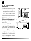
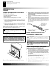
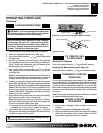
CONVENTIONAL FIREPLACE INSTALLATION
Conventional installation of this fireplace involves installing fireplace
along with the corner or cabinet mantel with hearth base accessories
against a wall in your home (see Accessories, page 32 and 33). Follow
the instructions below to install the fireplace in this manner.
Note:
The instructions below show installation using the cabinet
mantel and the G3000F/G3001U/G3004W/G3006F/G3007U se-
ries hearth base accessories. The hearth base accessory shown is
optional for this installation. You can install fireplace and cabinet/
corner mantel directly on the floor. The corner mantel accessory
cannot be installed with the G3000F/G3001U/G3004W/G3006F/
G3007U hearth base. The corner mantel can be paired with the
G3008F/G3009U/G3010F corner hearth base. If mounting fire-
place and cabinet or corner mantel to the floor, an optional G3005
Slim Base kit may be installed.
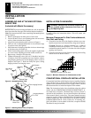
INSTALLATION CLEARANCES
WARNING: Maintain the minimum clearances. If
you can, provide greater clearances from floor, ceil-
ing, and adjoining wall.
Carefully follow the instructions below. This will ensure safe
installation.
Minimum Clearances For Side Combustibleaterial,
Side Wall, and Ceiling
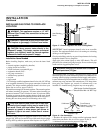
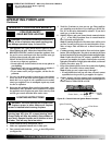
A. Clearances from the side of the fireplace cabinet to any com-
bustible material and wall should follow diagram in Figure 8.
Example:
The face of a mantel, bookshelf, etc. is made of
combustible material and protrudes 3
1
/2" from the wall. This
combustible material must be 4" from the side of the fireplace
opening (see Figure 8).
B. Clearances from the top of the fireplace opening to the ceiling
should not be less than 42 inches.
Figure 8 - Minimum Clearance for Combustible to Wall
*Minimum 16 inches from Side Wall
*
Example
Trim Hanging Screws
Assembled
Brass Trim
Hanging Notches
on Trim
INSTALLATION
Assembling and Attaching Optional Brass Trim
Installation Clearances
Conventional Fireplace Installation