


107156-01E
For more information, visit www.desatech.com
For more information, visit www.desatech.com
12
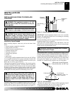
Pressure Testing Gas Supply Piping System
Test Pressures In Excess Of 1/2 PSIG (3.5 kPa)
1. Disconnect fireplace with its appliance main gas valve (control
valve) and equipment shutoff valve from gas supply pipping. Pres-
sures in excess of 1/2 psig will damage fireplace gas regulator.
2. Cap off open end of gas pipe where equipment shutoff valve
was connected.
3. Pressurize supply piping system by either using compressed
air or opening propane/LP supply tank valve.
4. Check all joints of gas supply piping system. Apply noncorrosive
leak detection fluid to all joints. Bubbles forming show a leak.
5. Correct all leaks at once.
6. Reconnect fireplace and equipment shutoff valve to gas sup-
ply. Check reconnected fittings for leaks.
CHECKING GAS CONNECTIONS
WARNING: Test all gas piping and connections
for leaks after installing or servicing. Correct all leaks
at once.
WARNING: Never use an open flame to check for
a leak. Apply a noncorrosive leak detection fluid to
all joints. Bubbles forming show a leak. Correct all
leaks at once.
Installation Items Needed
• 5/16" hex socket wrench or nut-driver
• Phillips screwdriver
• sealant (resistant to propane/LP gas, not provided)
1. Remove fireplace screen. Remove two screws that hold fire-
place screen in place for shipping. These screws are located
near top of screen. Discard screws. Lift fireplace screen up
and pull out to remove.
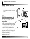
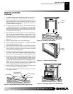
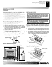
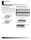
2. Remove screws that attach log base assembly to fireplace (see
Figure 19). Carefully lift up log base assembly and remove
from fireplace (see Figure 19).
Note:
If adding the G8000 series brick liner accessory, install it
now. Follow instructions in G8000 accessory kit.
CONNECTING FIREPLACE TO GAS SUPPLY
CAUTION: Do not pick up log base assembly by
burners. This could damage burners. Only handle
base by grates.
3. Route gas line (provided by installer) from equipment shutoff
through one of the access holes.
Figure 19 - Removing Log Base Assembly From Fireplace
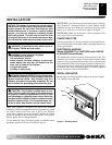
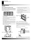
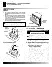
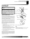
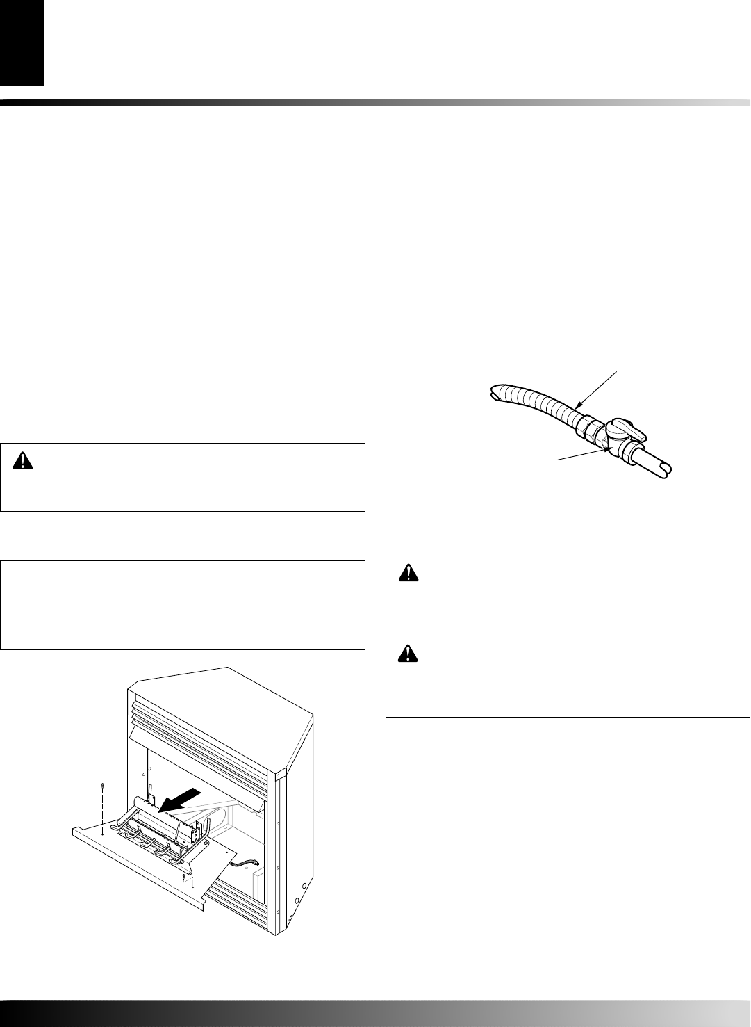
Figure 20 - Attaching Flexible Gas Lines Together
4. Attach flexible gas line to gas supply (see Figure 20). Check
connection of flexible gas line attached to gas regulator of fire-
place (see Figure 20).
5. Check all gas connections for leaks. See Checking Gas Con-
nections.
6. Replace log base assembly back into fireplace. Feed flexible
gas line into fireplace base area while replacing log base assem-
bly. Make sure the entire flexible gas line is in fireplace base
area. Reattach log base assembly to fireplace with screws re-
moved in step 2.
To Fireplace
Gas Regulator
Flexible Gas Line
from Equipment
Shutoff Valve
Equipment Shutoff Valve
Provided by Installer
➞
➞
To External
Regulator
NOTICE: Most building codes do not permit con-
cealed gas connections. A flexible gas line is pro-
vided to allow accessibility from the fireplace (see
Figure 20). The flexible gas supply line connection to
the equipment shutoff valve should be accessible.
INSTALLATION
Continued
INSTALLATION
Connecting Fireplace to Gas Supply
Checking Gas Connections