


107156-01E
For more information, visit www.desatech.com
For more information, visit www.desatech.com
13
13
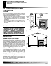
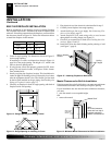
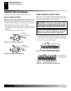
Equipment Shutoff Valve
Propane/LP
Supply Tank
INSTALLATION
Continued
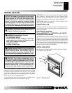
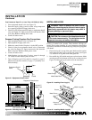
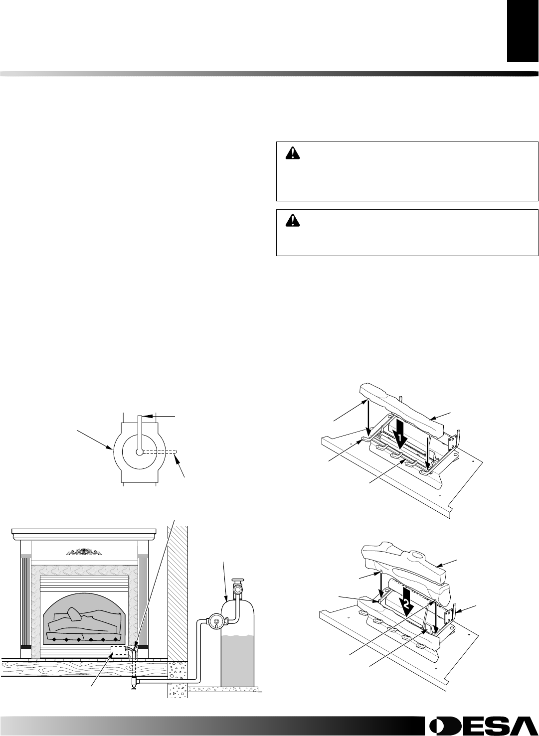
Figure 21 - Equipment Shutoff Valve
ON
POSITION
OFF
POSITION
Open
Closed
Equipment Shutoff
Valve
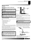
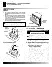
Figure 22 - Checking Gas Joints
Gas Control Valve
Test Pressures Equal To or Less Than 1/2 PSIG (3.5 kPa)
1. Close equipment shutoff valve (see Figure 21).
2. Pressurize supply piping system by either using compressed
air or opening propane/LP supply tank valve.
3. Check all joints from propane/LP supply to equipment shutoff
valve (see Figure 22). Apply noncorrosive leak detection fluid
to all joints. Bubbles forming show a leak.
4. Correct all leaks at once.
Pressure Testing Fireplace Gas Connections
1. Open equipment shutoff valve (see Figure 21).
2. Open propane/LP supply tank valve.
3. Make sure control knob of fireplace is in the OFF position.
4. Check all joints from equipment shutoff valve to thermostat
gas valve (see Figure 22). Apply noncorrosive leak detection
fluid to all joints. Bubbles forming show a leak.
5. Correct all leaks at once.
6. Light fireplace (see Operating Fireplace, pages 14 through
17). Check all other internal joints for leaks.
7. Turn off fireplace (see To Turn Off Gas to Appliance, page 15
[thermostat-controlled models] or page 17 [manually-con-
trolled models]).
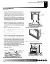
WARNING: Failure to position the parts in accor-
dance with these diagrams or failure to use only parts
specifically approved with this heater may result in
property damage or personal injury.
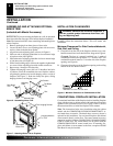
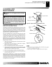
INSTALLING LOGS
Each log is marked with a number. These numbers will help you
identify the log when installing. It is very important to install these
logs exactly as instructed. Do not modify logs. Only use logs supplied
with heater.
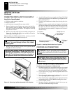
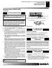
1. Place front log (#1) on top of the grate. Make sure the notches
in the bottom of the log fit over the grate prongs (see Figure
23). Push back of log flush with metal grate bar.
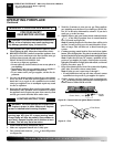
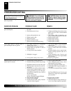
2. Rest middle log (#2) behind metal posts on front burner. Make
sure the grooves in the bottom of the log fit over the grate (see
Figure 24). Bring the log forward next to the metal posts.
CAUTION: Do not remove the data plates attached
to the heater base assembly. The data plates contain
important warranty and safety information.
INSTALLATION
Checking Gas Connections (Cont.)
Installing Logs
Figure 23 - Installing Front Log (#1)
Figure 24 - Installing Middle Log (#2)
Middle Log (#2)
Grate Prongs
Metal Grate Bar
Front Log (#1)
Notch
Metal Post
Metal Post
Groove
Groove
Grate