


CONNECTING GAS SERVICECONNECTING GAS SERVICE
CONNECTING GAS SERVICECONNECTING GAS SERVICE
CONNECTING GAS SERVICE
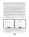
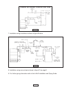
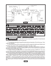
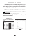
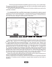
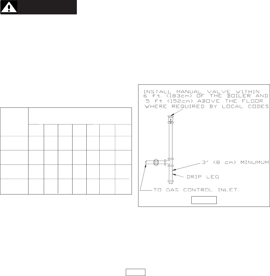
1. Connect gas service from meter to control assembly in accordance with ANSI Z223.1
and local codes or utility. A ground joint union should be installed for easy removal of gas
control for servicing. A drip leg or trap must be installed at the bottom of a vertical section
of piping at the inlet to the boiler. A pipe compound resistant to the action of liquified petroleum
gases must be used on all threaded pipe connections. Check with the local utility for location
of manual shutoff valve if required. See figure 13 below.
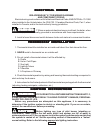
2. The gas line should be of adequate size to prevent undue pressure drop and never
smaller than the pipe size of the main gas control valve. See chart below.
3. To check for leaks in gas piping, use a soap and water solution or other approved
method.
WARNING: DO NOT USE AN OPEN FLAME.
4. Disconnect the boiler from the gas supply piping system during any pressure testing
of the gas piping. After reconnecting, leak test the gas connection and boiler piping before
placing the boiler back into operation.
PAGE 12
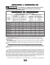
FIGURE 13
Nominal
Iron Pipe
Size
Maximum Capacity of Pipe in
Cubic Feet of Gas Per Hour
(Gas pressure = 0.5 psig or less, pressure drop =
.5 in.w/c)
Length of Pipe (Feet)
10' 20' 30' 40' 60' 80' 100'
1/2" 175 120 97 82 66 57 50
3/4" 360 250 200 170 138 118 103
1" 680 465 375 320 260 220 195
1.1/4" 1400 950 770 660 530 460 400
For additional information refer to “Table C” of the
National Fuel Gas Code Handbook.