


VENT DVENT D
VENT DVENT D
VENT D
AMPER INSTAMPER INST
AMPER INSTAMPER INST
AMPER INST
ALLAALLA
ALLAALLA
ALLA
TION TION
TION TION
TION
AND INSTRAND INSTR
AND INSTRAND INSTR
AND INSTR
UCTIONSUCTIONS
UCTIONSUCTIONS
UCTIONS
INSTALLATIONINSTALLATION
INSTALLATIONINSTALLATION
INSTALLATION
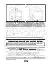
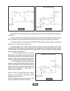
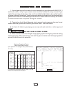
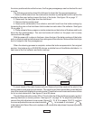
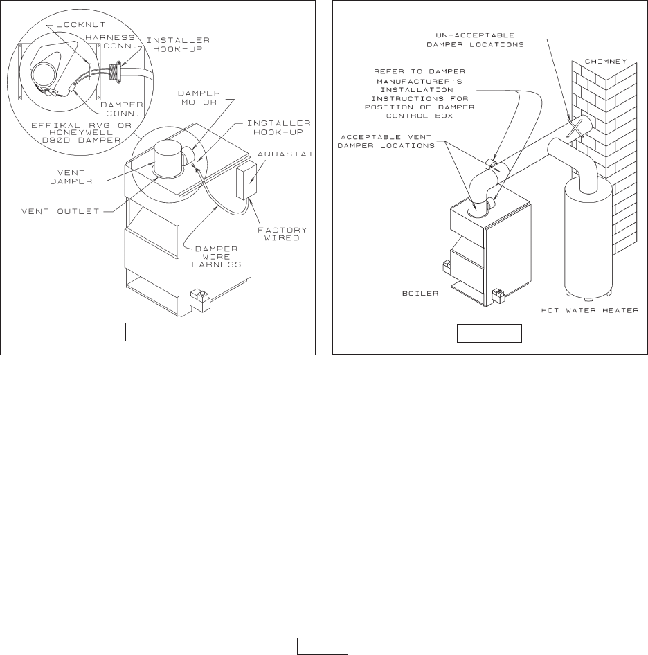
NOTE: Refer to Figure 11for steps 1 - 7.
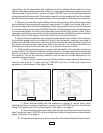
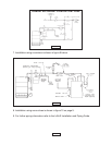
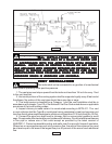
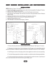
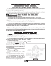
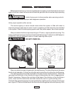
1. Place Vent Damper on or as close to vent outlet of boiler as possible. See figure 12 below.
2. Remove Vent Damper Motor cover.
3. Remove locknut from connector at the end of the Damper wire harness.
4. Feed Damper and Damper wire harness connectors through bracket hole on Damper
Motor frame.
5. Replace and tighten locknut onto Damper wire harness connector,
6. Plug Damper connector into socket on Damper Motor frame.
7. Replace Damper Motor cover.
8. Wire Damper in accordance with figure 11below.
INSTRUCTIONSINSTRUCTIONS
INSTRUCTIONSINSTRUCTIONS
INSTRUCTIONS
1. Ensure that only the boiler is serviced by the Vent Damper. See Figure 12, above.
2. Clearance of not less than 6 inches between Vent Damper and combustible material
must be maintained. Additional clearance should be allowed for service of Vent Damper.
3. Vent Damper must be in the open position when appliance main burners are operating.
4. The Vent Damper position indicator must be in a visible location following installation.
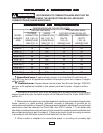
5. The thermostat's heat anticipator must be adjusted to match the total current draw of
all controls associated with the boiler during a heating cycle.
PAGE 11
FIGURE 11
FIGURE 12