


Model 5100-02-IT Combustible Gas Sensor Module
Page: 25
• Wiring terminations clean and correct.
6.5.4 MOISTURE TRAPS AND RAINSHIELDS
• Conduit seals and drains installed to avoid moisture build up in electronics enclosure. Water accumulation in
sensor module enclosures is a major cause of damage and system failures - take precautions to seal
electrical conduits and provide moisture traps and drains to avoid water damage
• Rain-shields installed where applicable.
6.5.5 STANDARD VOLTAGES
• Regulated DC Voltage to be applied to the sensor module must be between 10 VDC and 30 VDC.
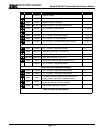
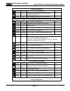
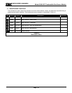
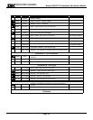
6.5.6 INSPECTION AND TROUBLESHOOTING GUIDE
The inspection and troubleshooting guide can be used to step through the system start-up and to determine the
corrective action if a fault occurs.
6.5.7 IF MODULE DOES NOT RESPOND TO GAS
1. Repeat calibration procedure.
2. Remove the gas and wait for the timer to completely count down.
3. Apply 50%LEL and verify that the sensor sees 50% LEL gas after calibration.
4. If the sensor still does not see gas, power cycle the unit and repeat calibration.
6.5.8 IF THE MODULE DOES NOT COME OUT OF WARM UP
1. Make sure the sensor is placed in an ambient room temperature environment.
2. Power cycle the sensor.
3. Ensure that the sensor is not exposed to combustible gas during warm-up.
6.5.9 IF THE MODULE DOES NOT DISPLAY THE CORRECT %LEL
1. Power cycle the unit.
2. Recalibrate the sensor.
6.5.10 IF THE DISPLAY SHOWS ‘NO SENSR’ –SENSOR FAILING
1. Power down the unit
2. Open the enclosure and unplug the sensor from the transmitter board.
3. Plug the sensor back into the transmitter board carefully and ensure a secure fit.
4. Power up the unit.
6.5.11 IF THE MODULE SHOWS “***CALIBRATION REQUIRED***”
1. Calibrate the module
6.5.12 IF THE MODULE SHOWS “***UNCALIB***”
1. Hold magnet to any key to acknowledge message
2. Calibrate the module
6.5.13 IF THE DISPLAY SHOWS ‘H’ (OR L) THEN THE LOCAL HIGH OR LOW ALARM IS ACTIVE
6.5.14 IF THE DISPLAY SHOWS ‘W’ – RADIO FREQUENCY INTERFERENCE
1. Remove source of interference.
6.5.15 IF THE DISPLAY SHOWS “C” – CALIBRATION MODE
1. Complete calibration or exit to operating mode.
6.5.16 OTHER ERROR MESSAGES – CALL FACTORY
1. E: OSC F1 Oscillator Fail