


Model 5100-02-IT Combustible Gas Sensor Module
Page: 10
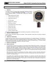
3.3 ENCLOSURE INSTALLATION
To protect the transmitter and sensor assembly they should be removed from the enclosure and preserved
until final installation and wiring termination.
Prior to installation and wiring.
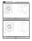
1. Remove the transmitter from the module housing by:
• Unscrew the two captive panel screws on the face plate.
• Lift the transmitter out of the housing.
• Unplug the sensor cable from transmitter connector J2.
• Remove the sensor assembly from the enclosure hub.
2. Install the module housing onto the end of the supply conduit and/or bolt into position as required.
NOTE
When housing earth grounding is required for the installation a grounding lug is located in the
base of the enclosure. Install the earth ground to under the green ground lug.
3.4 TRANSMITTER AND SENSOR INSTALLATION
When all pre-wire is complete:
1. Install sensor assembly in the open hub on the module enclosure. The sensor assembly thread
must be fully seated into the hub and tightened to maintain explosion proof assembly.
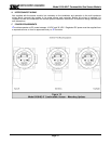
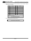
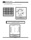
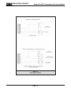
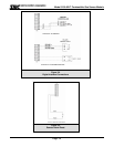
2. Connect the wires which return to the controller to transmitter connectors P1 and P2 (Figure 3-2)
according to Figures 3-3 (Analog Output), 3-4 (Digital Interface), 3-5 (Remote Alarm Reset).
3. Connect the sensor assembly cable to transmitter connector J2.
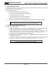
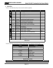
4. Reconnect any required auxiliary wiring to the applicable terminals according to project
requirements and Table 3-2.
5. Connectors P1 and P2 are removable to facilitate wiring termination. When reinstalling the
connectors pay attention to the connector orientation. See Figures 3-2, 3-3, 3-4, 3-5, etc.
NOTE
Connectors P1 and P2 are removable for easy wiring termination.