


Model 5100-02-IT Combustible Gas Sensor Module
Page: 5
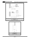
1.4.2 MODBUS OPERATION
All IT gas sensor modules have a Modbus RTU RS-485 serial interface to allow direct connection to any
standard PLC or DCS. The Module Address Switch (section 3.5) allows the user to select Modbus
addresses 1 thru 15. Switch position “0” allows the user to set addresses up to 254 using the s Menu (See
Table 4-3). Figure 3-4 provides the wiring terminations for Modbus connections.
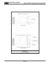
1.4.3 ANALOG OPERATION
All IT gas sensor modules have a 4-20 mA interface to allow direct connection to standard analog
indicators or PLCs. The standard Model 5100-02-IT provides a 4-20 mA analog interface which allows
power and loop connections. When IT modules are to be operated with analog interface, each module
requires individual home run wiring and no unique address is required. Figure 3-3 provides the wiring
terminations for 4-20 mA connections.
1.4.4 AUXILIARY RELAY OPERATION (APPENDIX E)
While the 5100-02-IT has three internal 0.25 amp relays (high alarm, low alarm and trouble) as standard,
an available option is an Auxiliary Relay Assembly, Part Number 5394-62, which provides 8 amp alarm
relays for each of the two conditions, low alarm and high alarm.
1.4.5 ENHANCED CONNECTION (APPENDIX F)
An Auxiliary Connection Assembly, Part Number 5394-61, applicable to Sentry and RS-485 installations
only, provides connections capable of accepting 12 AWG wire. Additionally, the enhancement acts as a
junction box providing connections for the next module in the run, when utilizing the Sentry multiplexing
capability.
1.4.6 AUXILIARY RS-485 MULTIDROP (APPENDIX G)
The Auxiliary RS-485 Multidrop Connection Assembly, Part Number 5394-64, provides the additional
terminal connectors to enable the user to connect the In/Out terminations of a RS-485 connection.
1.4.7 REMOTE SENSOR (APPENDIX D)
Extension kit 5394-51 can be used to remotely mount the sensor up to 50’ from the transmitter.
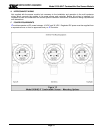
1.4.8 REMOTE ALARM RESET
An input is available for connection of remote alarm reset/acknowledge. Figure 3-5 provides the wiring
termination for connecting the remote alarm reset.
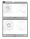
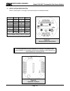
1.5 MECHANICAL
The sensor module is comprised of the following three primary components:
1.5.1 ENCLOSURE
Standard on the 5100-02-IT is an explosion-proof, rain-tight cast aluminum electrical housing with three ¾”
FNPT conduit hubs. The 5100-02-IT-SS has a 316 Stainless Steel enclosure. Both enclosure covers have
a viewing window. The design of the enclosure allows 3-way mounting choices as shown in figure 1-3. .
1.5.2 TRANSMITTER ELECTRONICS
Electronic Assembly consisting of one printed circuit board assembly mounted under a cover plate. Wiring
connections for power, signal interface and alarm relays are located on the back side of the display.
1.5.3 SENSOR ASSEMBLY
The sensor assembly includes an explosion proof housing containing the gas sensor and a wiring harness
for connection to the transmitter. The sensor assembly threads into one hub of the enclosure. The
exposed end of the sensor assembly is threaded to allow connection of a rain-shield or calibration gas
delivery fitting.