


Model 5100-02-IT Combustible Gas Sensor Module
Page: 12
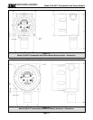
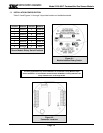
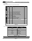
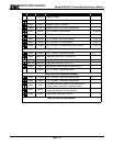
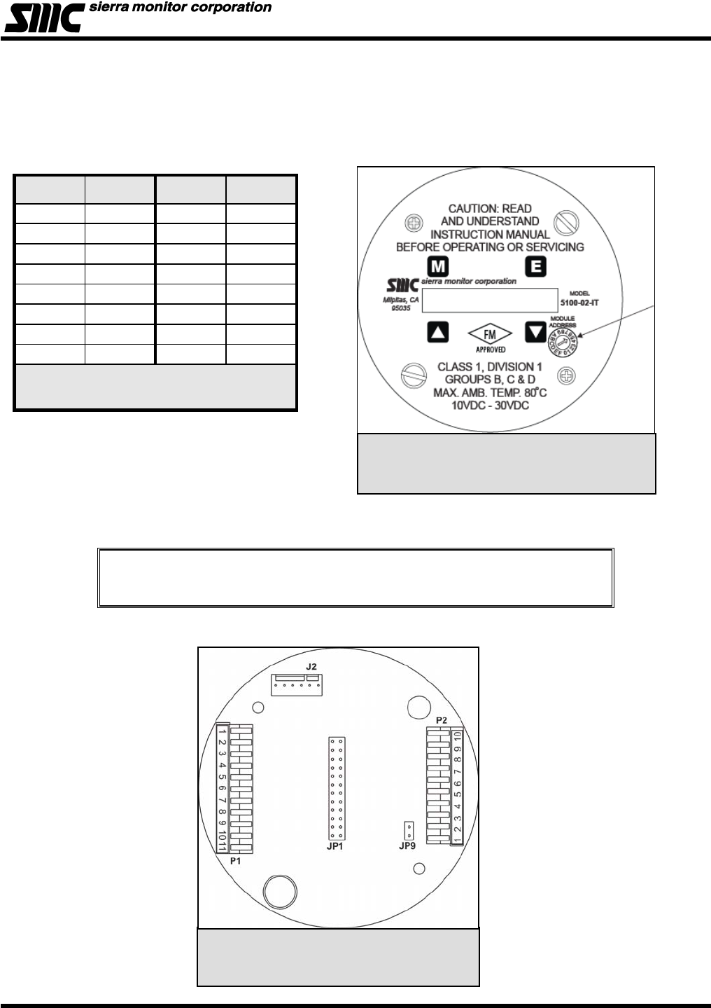
Figure 3-2
Connector Locations
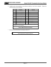
3.5 INSTALLATION CONFIGURATION
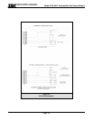
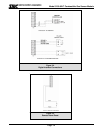
Table 3-3 and Figures 3-1 through 3-4 provide location and installation details.
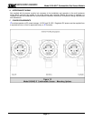
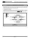
NOTE
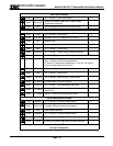
For Sentry applications only sensor addresses 1-8 are allowed. If using Modbus output
sensor addresses 1-15 are available. Position 0 allows the Modbus or Sentry address to be
set by software menu, in the range 16-254.
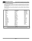
POSITION ADDRESS POSITION ADDRESS
1 Sensor 1 9 Sensor 09
2 Sensor 2 A Sensor 10
3 Sensor 3 B Sensor 11
4 Sensor 4 C Sensor 12
5 Sensor 5 D Sensor 13
6 Sensor 6 E Sensor 14
7 Sensor 7 F Sensor 15
8 Sensor 8 0 Select
Table 3-2
Sensor Module Rotary Switch Positions
Figure 3-1
Module Address Rotary Switch