


Model 5100-02-IT Combustible Gas Sensor Module
Page: 24
6.3
TRANSMITTER REPLACEMENT
The transmitter assembly should be replaced when it is determined that it is unreliable, noisy or cannot be
calibrated. This may occur due to age, corrosion or failed components.
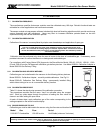
To replace the transmitter assembly:
a. Remove the cover of the main enclosure
b. Unscrew the two thumb screws in the top of the cover plate, lift the assembly and rotate 90
o
to relieve the
wiring service loop
c. Unplug the sensor connector from the transmitter
d. Plug connector into new transmitter (be sure to match numbers between connector and socket).
e. Restore power and allow a minimum of 3 hours for stabilization before re-calibration
6.4
SENSOR REPLACEMENT
The gas sensor which is located inside the sensor assembly housing can be replaced without replacement of the
housing. The gas sensor needs replacement when:
The “CAL-FAIL” message appears after calibration
The sensor output signal is noisy, causing erroneous gas level readings
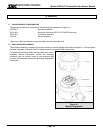
To replace the sensor:
a. Confirm that system power has been removed
b. Remove the gas sensor module enclosure cover,
c. Unscrew the two thumb screws in the top of the faceplate, lift the transmitter assembly and rotate 90
o
to
relieve the wiring service loop.
d. Unplug the sensor connector from the transmitter
e. Unscrew the old sensor assembly from the enclosure conduit hub. Remove the sensor assembly with its
harness
f. Unscrew sensor housing cover from the sensor (be sure to loosen the set screw first)
g. Carefully pull the old sensor straight up from the socket
h. Press the new sensor into the socket.
i. Reverse the preceding steps to install the sensor assembly.
j. Allow the new sensor to stabilize for a minimum of 3 hours and then calibrate using the procedure in Section
5.
6.5
INSTALLATION INSPECTION
Prior to system start-up or trouble shooting, the entire system should be visually inspected. The following are
guidelines for that inspection:
6.5.1 CONTROLLER INSTALLATION
• Controller installed in conformance to instruction manual recommendations.
• AC power is correctly grounded.
• Hot AC and relay connections have safety covers installed.
6.5.2 CABLING INSTALLATION
• All splices are soldered or via terminal block.
• Cabling is away from sources of electrical noise where possible.
• Connector P2, terminals P2 1, 2, 3 on sensor module are connected to Sentry controller as Power, Signal,
Ground, respectively.
6.5.3 SENSOR MODULE INSTALLATION
• Module installation in conformance with this manual.
• Modules accessible for calibration.