


Model 5100-02-IT Combustible Gas Sensor Module
Page: 9
3. INSTALLATION
NOTE
All IT modules are factory pre-configured and calibrated.
All modules are tagged to indicate the configuration including the sensor module number.
Identify all components during unpacking and install using the factory configuration.
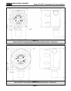
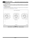
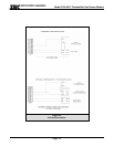
3.1 SENSOR MODULE LOCATIONS
Select locations for each sensor module based on the following:
• Modules should be placed close to the potential source of gas.
• Modules should be placed in areas accessible for calibration.
• Sensors should be pointed down and the conduit should include an inverse trap to reduce moisture
(condensation) from accumulating in the electronics enclosure.
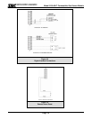
• Remote calibration fitting (5360-00) can be used to facilitate calibration gas delivery. Run polyurethane
tubing (1/4” O.D. x 1/8” I.D.) from fitting to an accessible location.
3.2 WIRING
3.2.1 ANALOG 4-20 MA OPERATION
The 4-20 mA output for the 5100-02-IT can be either 3-wire (using the 5394-61 Connector Board) or 4-wire
operation. If using 3-wire operation, use a minimum of 18 AWG, shielded, 3-conductor cable up to 2000’.
For 4-wire operation, use a minimum of 2 each, 18 AWG, twisted, shielded, pair up to 2000’.
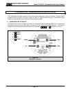
3.2.2 MODBUS OPERATION USING RS-485 CONNECTION
Use a minimum of 18 AWG, 2 conductor for DC power connection. No shield required. In addition use a
minimum of 24 AWG, low capacitance, shielded data cable for RS-485 half duplex communication. The
installation may be planned in a manner which provides up to 32 sensor modules on a single home run.
3.2.3 SENTRY OPERATION USING SMC SENTRY CONNECTION
Use a minimum of 18 AWG, 3-conductor cable up to 2000’. The cable may or may not be shielded. We
recommend shielded cable in circumstances that there could be RF or EM interference present. Shield to
be terminated and grounded only at the Sentry controller. Shield must be cut and dressed at the module
end so that no part of it comes in contact with the conduit or ground.
NOTE:
Be sure to follow all local electric code and safety requirements when installing the 5100-02-IT Gas Sensor Module
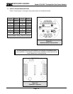
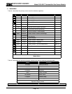
3.2.4 GENERAL
Install conduit as required by local code or construction specifications. When sensor modules are to be
multiplexed for Sentry or RS-485 communication two alternatives may be planned:
• Install splice boxes above each sensor module. Use multi-position positive contact terminals to
connect daisy chain wiring and provide a pigtail to connect to the sensor module transmitter board.
• Use Auxiliary Connection Assembly, Model 5394-61. The Auxiliary Connection Assembly plugs into
the sensor module transmitter and provides daisy chain wiring.
NOTE
The drain wire of shielded cable must NOT be used as one of the conductors.
Installation and wiring must be in accordance with the National Electrical Code. Temperature
rating of cable wire must be at least 75
o
C. If cable runs through higher temperature
environments, it must be specified for that environment.