9
Installation
MV 6 Y G W
O B
RC RH
H
MVWRHRCGYOB6
G
Y
5
3
C
2
D E
4
RH
W
1
L
M
KJ
I
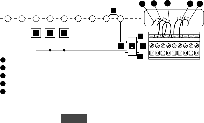
Figure 3. Typical wiring diagram for heat only, cool only, & heat/cool single transformer systemFigure 3. Typical wiring diagram for heat only, cool only, & heat/cool single transformer system
Figure 3. Typical wiring diagram for heat only, cool only, & heat/cool single transformer systemFigure 3. Typical wiring diagram for heat only, cool only, & heat/cool single transformer system
Figure 3. Typical wiring diagram for heat only, cool only, & heat/cool single transformer system
1
From heating system
2
From 24 VAC transformer
3
Red jumper wire (provided)
4
Red jumper wire (provided)
5
Red jumper wire (provided)
NOTE: Ensure that RED RH/RC jumper wire (provided with thermostat) is
connected between thermostat’s RH and RC terminals for proper
operation with this system.
NOTE: For three-wire heat only system, connect terminals
GG
GG
G,
WW
WW
W, and
RHRH
RHRH
RH.
For cool only system, connect terminals
YY
YY
Y,
GG
GG
G, and
RHRH
RHRH
RH.
See page 10 for letter identification.


