


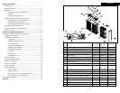
SYSTEM CHECKOUT
WARNING:
The following procedures must be conducted by a qualified HVAC contractor or repair
person ONLY. These procedures will expose hazardous electrically energized charged
components. Disconnect power between checks and proceed carefully.
1. The HVAC system blower should be turned OFF.
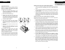
2. Switch the ON/OFF rocker switch to the ON position. The bright red segment of the
rocker switch should be visible.
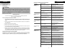
3. Inspect both the Green INPUT POWER light and the Red CELL ENERGIZED light:
System With Air Cleaner INPUT POWER From Dedicated Power Source
• The Green INPUT POWER light should illuminate and remain illuminated.
• The Red CELL ENERGIZED light should illuminate and should go out in
approximately 20 to 60 seconds. This is the normal time for the electronic Air
Flow Sensor to complete its stabilization period. The Red light will come back
on when the HVAC system blower begins to operate. See the section entitled
AIR FLOW SENSOR pg. 2, for more information.
System With Air Cleaner INPUT POWER From HVAC System
• Neither Green INPUT POWER light nor Red CELL ENERGIZED light should
illuminate.
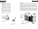
4. Wait approximately one minute and turn the HVAC system blower ON. Most
thermostats have a setting that will allow you to operate the blower manually. If
not, set the thermostat so that either hot or cold air begins to flow through the duct
work.
System With Air Cleaner INPUT POWER From Dedicated Power Source
• The Green INPUT POWER light should remain illuminated.
• The Red CELL ENERGIZED light should illuminate within approximately 20 to
60 seconds, and remain illuminated while the HVAC system blower is in
operation.
System With Air Cleaner INPUT POWER From HVAC System
• The Green INPUT POWER light should illuminate and remain illuminated.
• The Red CELL ENERGIZED light should illuminate within approximately 20 to 60
seconds and remain illuminated while the HVAC system blower is in operation.
5. Check to make sure that the Red CELL ENERGIZED light goes out with the following
conditions:
• Front Panel Assembly is removed
• ON/OFF switch is switched to the OFF position
• HVAC system blower is not running
Installation
19
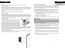
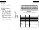
REPLACING THE IONIZING WIRES
Instances of the Ionizing Wires breaking are minimal due to the constant tension design and
fixed location of the Ionizing Wire supports. When an Ionizing Wire breaks, the efficiency of the
Electronic Air Cleaner will decrease slightly. However, the unit will continue to operate with a
broken Ionizing Wire as long as the broken wire has not caused a short in the secondary circuit
of the unit. Remove all loose and broken wires as soon as they are identified.
We recommend contacting a qualified HVAC contractor for replacement parts and/or servicing.
Ionizing Wires are supplied in a coiled spring configuration, with a clinch nut on each end of the
wire. Replacement requires a pair of needle nose pliers. Exercise caution in removing any broken
wires in the Ionizing-Collecting Cell. The removal of broken wires will prevent accidental
shorting of the cell and reduce the need for further maintenance.
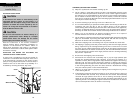
Use the following procedure when replacing an Ionizing Wire:
1. Turn Air Cleaner ON/OFF switch to OFF position. Wait 15 seconds. Remove the Front Panel
Assembly and remove the Ionizing-Collecting Cells from the unit.
2. Carefully remove all remains of the broken wire from the cell.
3. Grip the new wire at each end with your thumb and index finger. While stretching the wire
to approximately 6”, allow one end of the wire to uncoil between your thumb and index
finger.
4. Place one end of the wire in the slot of the stainless steel wire support located on the
Ionizing-Collecting Cell as viewed from the front of the cell. This support is partially covered
by the cell brace in front of the support.
5. Grip the other end of the Ionizing Wire with needle nose pliers and insert the terminated
end of the wire into the slot in the wire support on the opposite end of the Ionizing-
Collecting Cell.
6. The wire should have sufficient tension to be self supporting and remain suspended
between the slots in the wire supports.
Maintenance
6
For Qualified HVAC
Installer Only
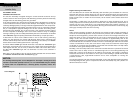
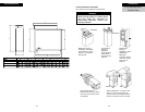
CLEANING THE AIR FLOW SENSOR
If the air cleaner is installed in a location that is dusty and dirty, the sensor (thermistor) on the
AFS can become coated with dirt and lint. This coating can insulate the AFS and keep it from
operating properly. To clean the thermistor, turn the unit OFF, dip a cotton swab in rubbing
alcohol and carefully insert into the 3/16” diameter hole located on the front right hand side of
the Power Tray Assembly (when facing the unit). Carefully twirl the cotton swab between your
fingers, making sure the tip is lightly in contact with the gray disc (thermistor), cleaning the
insulating coating from the thermistor.