


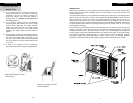
LOCATION SELECTION
Remember to select a location that is readily accessible
for periodic inspection and cleaning of the the Pre-
filters and Ionizing-Collecting Cells. Allow a minimum
of 24” clearance in front and 12” clearance above the
air cleaner for component removal and service space.
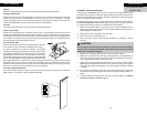
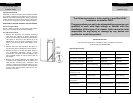
DIRECTION OF AIRFLOW THROUGH THE AIR CLEANER
For left to right airflow:
This air cleaner is factory set for left to right airflow
when you are facing the Front Panel Assembly.
For right to left airflow:
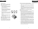
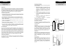
1. Remove the Pre-filters and Ionizing Collecting
Cells from the cabinet. A plastic positioning
spacer is located inside the bottom of the cabinet.
This spacer is secured to the cabinet by a #6
Phillips drive screw to assure installation of the
Cells in the correct position with respect to air
flow.
2. Remove the screw and reposition the spacer in
the alternate hole in the bottom of the cabinet.
3. Replace the screw to ensure the plastic spacer is
not accidentally dislodged during normal
maintenance. The spacer must be installed in the
hole provided nearest to the air leaving side of
the cabinet.
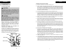
4. Remove the Ionizing-Collecting Cell handle and
re-attach to the opposite end of the cell(s). Turn
Cells around, reversing their orientation and
replace in cabinet and replace Pre-filters on the
air entering side of the air cleaner. The directional
arrows on the cell end plates must point in the
direction of airflow.
Installation
14
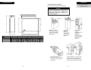
The following section is to be used by a qualified HVAC
contractor or installer ONLY.
These procedures are not to be attempted by any person not
qualified to work with high voltage or familiar with the
installation of this type of air cleaner. Seller cannot be held
responsible for any injury or damage by any person not
qualified to install this product.
INSTALLER HELP LINE
If you have any questions on installation issues or problems, please call
Technical Support 866-829-2440
Installation
For Qualified HVAC
Installer Only
11
For Qualified HVAC
Installer Only
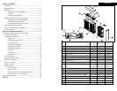
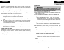
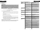
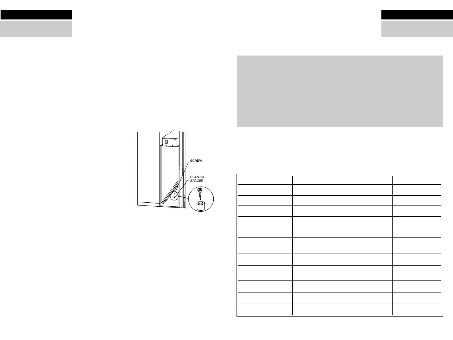
Model
Size
Part Number 120V/50-60Hz
Part Number 240V/50-60Hz
Maximum Rated Airflow
Maximum Pressure Drop
Cell Weight
(2 Cells in ea. unit)
Unit Weight
Maximum Power
Consumption
Electrical Output
Classification
Optional Accessories
HE Plus 1400
(16x25)
455601-001
455601-010
1400 CFM (2380m/hr)
.11 inch w.g. @1400 CFM
10 lbs ea. (4.5 kg)
32 lbs. (14.6 kg)
40 watts
2.5 MADC @ 6200 VDC
UL/CE
Charcoal After Filter
HE Plus 1400
(20x20)
455603-001
455603-010
1400 CFM (2380m/hr)
.11 inch w.g. @1400 CFM
9 lbs ea. (4.1 kg)
36 lbs. (16.4 kg)
40 watts
2.5 MADC @ 6200 VDC
UL/CE
Charcoal After Filter
HE Plus 2000
(20x25)
455600-001
455600-010
2000 CFM (3400m/hr)
.14 inch w.g. @2000 CFM
12 lbs ea. (5.5 kg)
36 lbs. (16.4 kg)
48 watts
3.2 MADC @ 6200 VDC
UL/CE
Charcoal After Filter
Technical Specifications