


SECONDARY CIRCUIT POWER SUPPLY
If the Red CELL ENERGIZED light remains out with the Ionizing-Collecting Cells
removed from the cabinet, the power supply is defective. Specific problems in the
Power Tray Assembly can be isolated by using a Multimeter and High Voltage
Probe to check the output voltages.
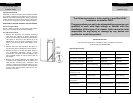
To check the secondary circuit, a high voltage meter is required. See the section
entitled RECOMMENDED SERVICE TOOLS (pg. 20). To check for proper operation,
it is imperative that the procedure be followed as outlined below:
1. Make sure the HVAC system is operating, the air cleaner ON/OFF switch is
ON, and air cleaner input voltage is correct (120V, 50-60Hz for 120V units and
240V, 50-60Hz for 240V units).
2. Remove Front Panel Assembly from air cleaner.
3. Remove Power Tray Assembly Cover.
4. Check the high voltage contact board assembly for damage or carbon
tracking.
CAUTION:
The cell contacts must be visually checked for corrosion, excessive dirt build-up,
and electrical arc tracking (Carbon path from stainless steel spring to grounded
metal). Clean or replace as required.
5. Replace both Ionizing-Collecting Cells in the air cleaner cabinet.
6. Make test connections from the High Voltage Probe to the Multimeter in
accordance with the probe’s instruction manual. The Multimeter should be
set for reading DC voltage at 20 volt full scale.
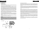
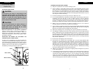
7. Attach the High Voltage Probe ground lead to the air cleaner cabinet. While
depressing the safety interlock switch lever, touch the ionizer wire support
with end of the High Voltage Probe. The meter reading should be 6.2 kVDC
+ .2 kVDC.
8. If no voltage is measured, remove the first Ionizing-Collecting cell and check
the second cell by repeating step #7. The meter should read 6.2 kVDC + .2
kVDC.
9. If proper voltage is measured, the first cell is shorted. Refer to COMMON
TROUBLESHOOTING TECHNIQUES (pg. 9).
Troubleshooting
23
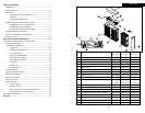
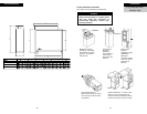
Cabinet
Mounts to existing ductwork; houses the Ionizing-Collecting Cells and Pre-filters.
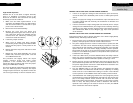
Ionizing-Collecting Cells
Collect the dust, dirt and other particulates in the air. They contain the ionizing and collecting
sections. The cells must be installed with the ionizing wires on the air intake side. A spring
contact is located on the top of each cell and must be in the position to make contact with the
contact board assemblies on the bottom of the Power Tray Assembly.
Pre-filters
Trap large particulates before they enter the Ionizing-Collecting Cell.
Power Tray Assembly
Contains the indicating lights, solid-state power supply, contact boards and electrical controls
including the ON/OFF switch and safety interlock switch. A power cord at the rear of the 120 volt
Power Tray allows the unit to be connected to a standard 120 volt outlet. A wiring compartment
is provided on all models at the rear of the Power Tray allowing the option to permanently wire
the unit directly to the HVAC System Control.
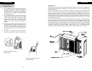
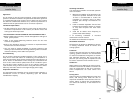
Air Flow Sensor (AFS)
Controls the operation of the unit by sensing the movement
of air within the duct. This helps to reduce power usage.
The AFS is designed to provide an efficient and reliable
method of controlling the operation of the air cleaner when
the installer is unable to wire the unit directly into the HVAC
System Blower Control Circuit. The AFS utilizes a thermistor,
which when electrically powered, heats up to approximately
130° F. The AFS stabilizes at this temperature and while the
HVAC System Blower is in operation, air flows through the ductwork, creating a vacuum effect
that pulls cooler air over the hot surface of the thermistor. This air movement cools down the
thermistor which allows the AFS to register that the HVAC System blower is moving air and the
Electronic Air Cleaner must be powered to provide air cleaning.
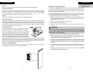
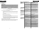
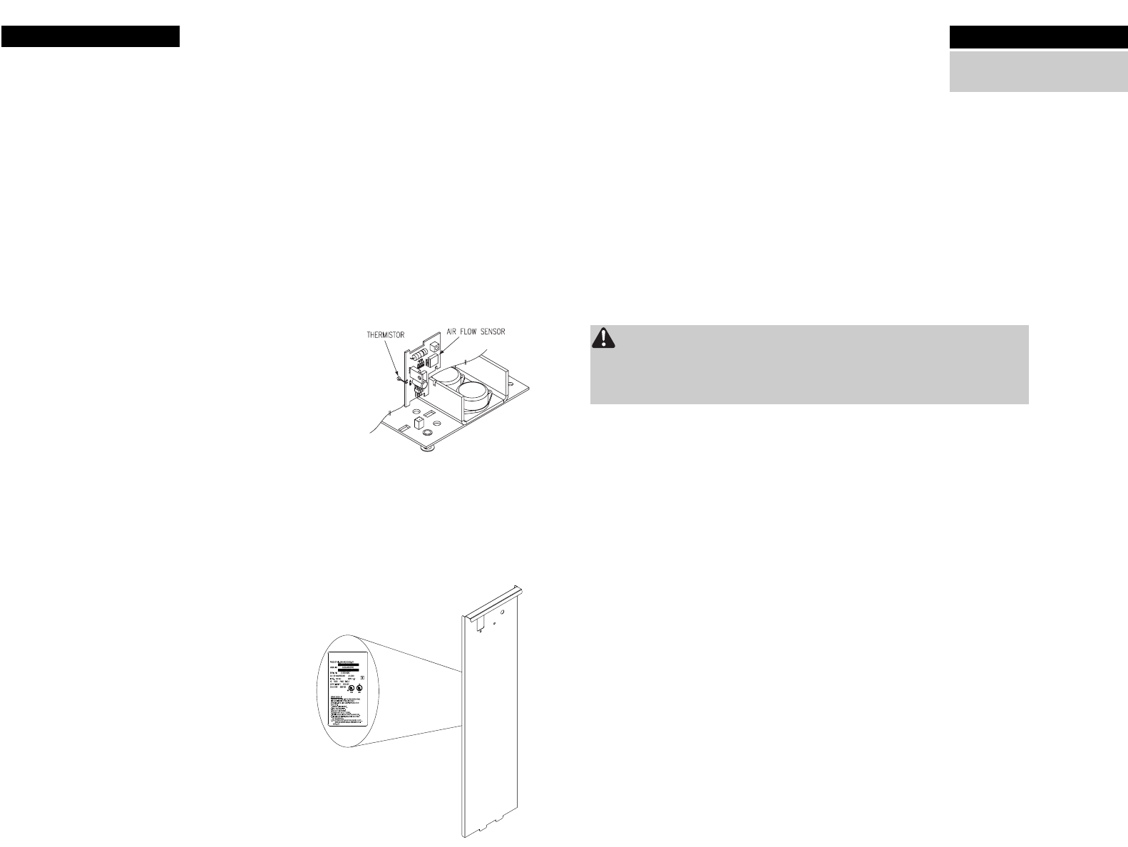
Air Cleaner Model Identification
The model number and part number for your Electronic Air Cleaner can be found on the data
label located on the inside of the Front Panel Assembly.
Unit Components
2
For Qualified HVAC
Installer Only