


Controls
RT-SVX20A-E434
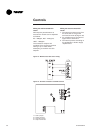
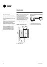
Trane THS01,THS02, THP01 and
THP02 Thermostats are directly
connected to RTRM board
(J7 connector).
Trane THS03 and THP03 thermostats
are directly connected to RTRM
board (J6 connector).
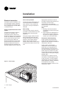
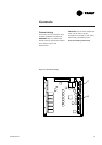
Install the electrical link between the
thermostat (thermostat terminal
strip) and the unit (J6 or
J7 connector) in compliance with
the interconnection diagram. The
low voltage wiring must not be laid
in the same pipes as the power
cables.
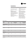
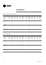
The sizes and lengths of the
thermostat connection wires are
given in Table 39. The total
resistance of these control cables
must not exceed 5 ohms. If the
resistance exceeds this value the
thermostat may not operate with
the same precision.
Table 39 - Zone sensor wire and
maximum length
Wire size
(mm²)
Maximum
wire lengh
(m)
0,33 45
0,5 76
0,75 115
1,3 185
2300
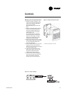
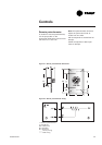
Unit controlled by BAS
Each unit must be equipped with a
TCI-R board. A communication bus
(twisted shielded pair) must link
each TCI-R to the Trane Roof Top
Manager (RTM) or to the
communication gateway (in the
case of an external BAS). Connect
one temperature sensor to each
unit. LonTalk
®
communication
interface LTCl-R board allows ICS
communication between a
ReliaTel™ unit and LonTalk
®
communication applications.
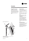
Unit controlled by Tracker™
supervisor
The units must also be equipped
with the TCI-R communication
board. One remote sensor is
required on each unit for a constant
flow volume. In the case of a
variable flow installation
(VariTrac™) these sensors must not
be installed. A twisted shielded pair
must be used for the
communication link. The main
functions of the Tracker™ supervisor
are control of setpoints, timetable
management (Programming) and
display of faults. For more details
refer to the supervisor
documentation.