


Installation
RT-SVX20A-E414
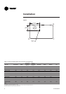
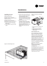
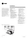
Filter installation
To gain access to filters, remove the
supply fan access panel on
downflow units and the filter access
panel on the end for horizontal
units.
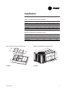
Number and size of filters is
determined by size and
configuration of the unit. If
disposable filters were chosen as an
option, they are shipped in the
supply fan section.
CAUTION! Do not operate unit
without filters in place.
The maximum pressure drops
allowable on filters are:
EU2/G2: 120 Pa
EU4/G4: 150 Pa
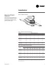
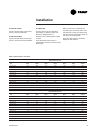
Table 7 - Filter arrangement
Unit
EU2/G2 EU4/G4
Quantity Size Quantity Size
TSD/TSH/YSD/YSH/WSD/WSH 060 2 (508x762x25) 2 (500x750x25)
TSD/TSH/YSD/YSH/WSD/WSH 072 4 (406x635x50) 4 (395x625x50)
TSD/TSH/YSD/YSH/WSD/WSH 090 4 (406x635x50) 4 (395x625x50)
TSD/TSH/YSD/YSH 102 4 (508x635x50) 4 (500x625x50)
TSD/TSH/YSD/YSH 120 4 (508x635x50) 4 (500x625x50)
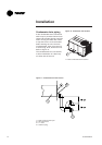
Supply fan adjustment
Use the following procedure to
determine the proper adjustment of
the supply fan for a specific
application.
1. Determine total external static
pressure about system and
accessories.
• Obtain the design airflow rate
and the design external static
pressure drop through the
distribution system.
• Add static pressure drop of the
accessories installed on the unit.
(Table 9)
• Add the total accessory static
pressure drop (from step 1b) to
the design external static
pressure (from step 1a). The sum
of these two values is the total
system external static pressure.
2. Using the Tables 10 through 35 to
find the external static pressure
that most closely approximates
total system external static
pressure. Then locate the
appropriate airflow rate for your
unit. The value obtained
represents the brake horsepower
for the supply fan motor and the
fan RPM.
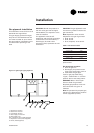
3. Adjust motor sheave according
to Table 8.