


Installation
RT-SVX20A-E430
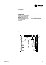
Electrical connection
The electric panel is located in the
unit compressor section. Remove
the compressor access panel. The
unit is designed to run with 400 V
+/- 5%/50 Hz/ 3 ph.
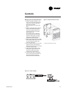
Factory supplied disconnect switch
(option)
The disconnect switch is factory
mounted. It is located in the
compressor section. Mount the
disconnect switch onto the exterior
of the unit, between the condenser
coil and the electrical panel (near
the unit top corner). Wire the
disconnect switch from the power
terminal block in the panel to the
disconnect switch with the wire
bundle provided by following the
electrical diagram found in the unit.
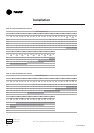
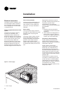
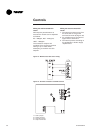
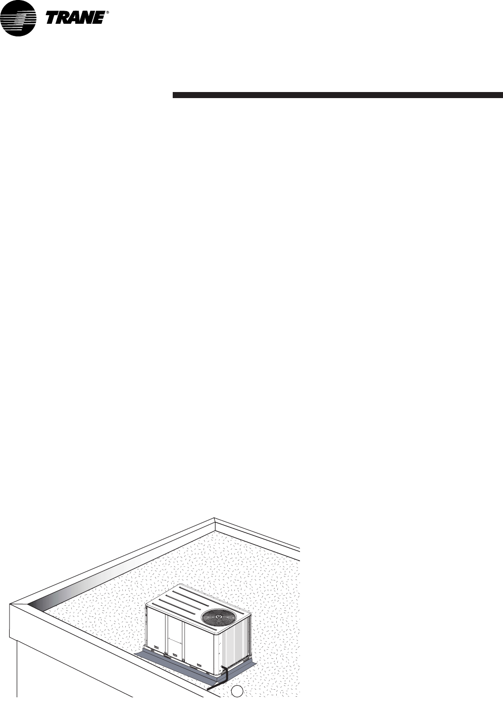
Figure 13 - Power supply
1 = Power supply
1
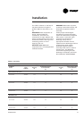
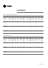
Over current protection
The branch circuit feeding the unit
must be protected in accordance
with national or local codes and
maximum unit amps indicated in
Table 36.
Power wiring
The unit's power supply must be
provided by 4-wire cable with cross-
sectional areas complying with
legislation.
The power supply cables must be
laid in leak-tight pipes and pass
through the bottom of the electric
panel for units without electric
heaters and through the heat
section when electric heater option
is selected. The cables must not be
taut.
Appropriate connectors must be
provided. Flexible pipe supports are
required to prevent noise
transmission in the building's
structure. Ensure all the connections
are tightened.
Note:
1. Earthing must be executed in
compliance to national and local
legislation.
2. The machines are designed for a
short-circuit current of 10 kA. In
the event of a higher application,
contact your local sales office.
Compressor electrical phasing
Proper phasing of the electrical
power wiring is critical for proper
operation and reliability of the scroll
compressor and fans.
Proper rotation of the scroll
compressor must be established
before the unit is started. This is
accomplished by confirming that
the electrical phase sequence of the
power supply is correct. The motor
is internally connected for clockwise
rotation with the inlet power supply
phased A,B,C.
The direction of rotation may be
reversed by interchanging any two
of the line wires. It is this possible
interchange of wiring that makes a
phase sequence indicator necessary
if the operator is to quickly
determine the phase rotation of the
compressor motor.