


35
RT-PRC016-EN
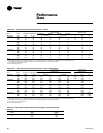
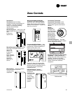
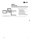
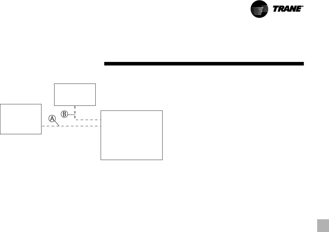
For specific wiring information, see the installation instructions.
All wiring except power wires is low voltage.
All customer supplied wiring to be copper and must conform to NEC or CEC and local electrical codes. Wiring shown dotted is to be furnished and installed by the customer.
DISCONNECT
SWITCH
(BY OTHERS)
ROOFTOP
UNIT
ZONE SENSOR
OR THERMOSTAT
Jobsite
Connections
Zone Sensors — Typical Number Of Wires
A — Manual Changeover . . . . . . . . . . . . . . . . . 4
Manual/Auto Changeover . . . . . . . . . . . . . 5
Manual/Auto Changeover with
Status Indication LED’s . . . . . . . . . . . . . 10
Programmable Night Setback with
Status Indication LED’s . . . . . . . . . . . . . . 7
Thermostats — Typical Number of Wires
A — 3 wires, 24-volts, Cooling Only
4 wires, 24-volts, with Electric Heat
B — 3 Power Wires + 1 Ground Wire (three phase)
2 Power Wires + 1 Ground Wire (single phase)