56
VAV-SVN01E-EN
Installation
of Diffusers
General
All units must be installed upright and
level as indicated by the arrow on the
side of the units. Return air slots should
be placed perpendicular and offset to
the slot diffusers to avoid short-
circuiting of air distribution patterns.
Place the unit in its approximate final
position and check that it is upright and
level. For single- slot units, engage
the back of the diffuser over the t-bar
with an edge and both ends resting on
the t-bar. For double-slot units, slide
the unit over the t-bar. For center-
notch units, place diffuser over the
t-bar, straddling it across a t-bar and
resting on the units ends.
If the unit has a fire damper, make sure
that the damper is still fully open.
Diffuser discharge must always be
flush with the ceiling tiles to assure the
proper airflow (Coanda effect).
Diffusers require specific installation
information when mounting to a
desired ceiling type. Select the ceiling
type that closely matches the job site
application and use the following
procedures.
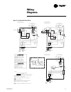
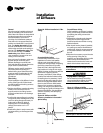
T-Bar Ceiling
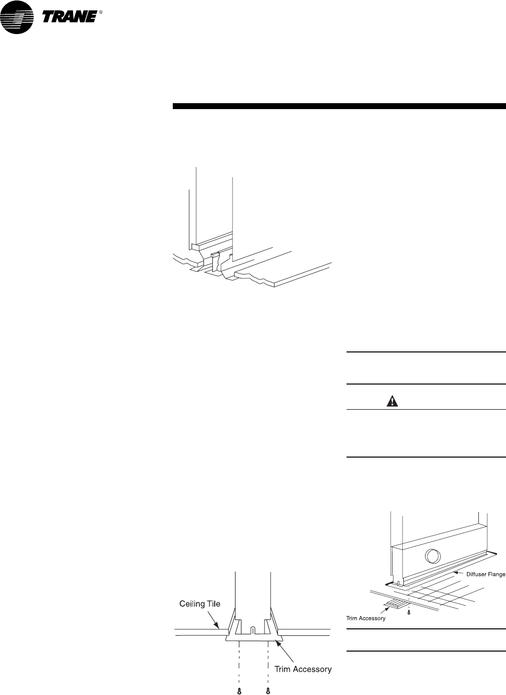
Finish installation of the diffuser in t-bar
ceiling. (See Figure 29.) Follow these
procedures before the ceiling construc-
tion is completed.
1.Position the diffuser at each end resting
directly on the structural t-bar for
support and the t-bar fitting into the
channel provided at the unit discharge
air throw.
2.A ceiling tile support flange is provided
on each side of the discharge slot of the
unit. Trim ceiling tile approximately 1½
inches each to allow for width of
discharge slot. For revealed edge
ceilings, tile must be cut in a “Z”
pattern.
3.Install ceiling tiles in usual manner with
cut edges resting on the flanges of the
air slot.
Figure 29 – Diffuser Installation in T-Bar
Ceiling
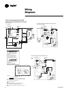
Concealed Spline Ceiling
Follow these procedures to finish
installation of control and satellite
diffusers and concealed spline for
suspension ceilings before completing
the ceiling construction (Figure 30).
Place the units in their approximate
final positions. If using the trim angle
diffuser, its slots must be even with the
spline level. If applying the trim
accessory, the bottom of the diffuser
must be level with the finished ceiling.
If installing the trim accessory, insert
the trim into the ceiling opening from
below and engage the diffuser slot to
the trim t-bar structure. With bottom
flange of trim accessory against the
ceiling, and using the pre-drilled holes
in the flange as a guide, drill holes in the
flange of the diffuser. Join the diffuser
and trim accessory with self-taping
sheet metal.
Figure 30 – Diffuser with Trim
Accessory Installation in Concealed
Spline Ceiling
CAUTION
CAUTION
Drywall/Plaster Ceiling
Finish installation of diffusers in plaster
ceiling. Follow these procedures before
completing the ceiling construction
(Figure 31).
1.Suspend the units above the intended
ceiling level and their approximate
horizontal positions and finish running
flexible ductwork.
2.After drywall and/or plaster is installed,
cut openings to receive the diffuser air
outlets. Also, allow for access openings
to complete installation and service of
the unit.
3.Slide the trim accessory up and into the
ceiling opening. Using the rim
accessory as a template, drill four guide
holes in the lip of the diffuser slot.
Lower the unit onto the trim frame and
attach with the sheet metal screws.
Note: The bottom of the throat section
must be parallel to the ceilings for proper
air distribution.
Equipment Damage!
Do not install trim frame into ceiling
using screws. When diffuser is placed
on the trim frames, it will pull out.
Plaster trim frame attaches with 2–4
tension clips on the side of the diffuser.
Figure 31 – Diffuser with Trim
Accessory Installation in Plaster Ceiling


