VAV-SVN01E-EN 31
Duct Connections
All VariTrane units should be provided
with a minimum of 1.5-duct diameters
of straight duct prior to the inlet of the
unit. It is recommended that at least 48
inches of straight duct be provided
from the discharge of the units prior to
any take-offs or transitions. This is a
requirement for electric heat fan-
powered units used in
applications with 100%
downward discharge.
Note: In order to maintain the UL rating
for VariTrane electric coils, there must be
four feet of straight unlined ductwork
downstream of the reheat coil prior to
any diffuser takeoffs.
After all connections are made, check
that the entire ductwork system is
airtight. In some high-pressure
systems, duct sealer may be necessary.
Provide insulation around the entire
inlet collar (all the way to the unit
casing).
Use caution not to damage the flow
tubes when making ductwork
connections or insulating.
Cut “slits” in the insulation for the flow
tubes and secure with duct tape.
If the unit is to be installed in a location
with high humidity, external insulation
around the heating coil should be
installed as required.
Water Coil Connections
Water coil piping connections will be
3/8” or 7/8” OD.
If necessary, you can change the coil
connection from left-handed to right-
handed (and vice-versa) by
disconnecting the coil from the unit
and rotating the coil “like a steering
wheel” 180°.
The inlet piping should always be
connected to the bottom connection of
the coil regardless of handedness.
Care should be taken to properly
support the water coil piping
connections while connecting the
adjoining pipe.
It is recommended that piping to the
water coil should be done after field-
mounted controls, external insulation,
and ductwork connections have been
completed.
Do not connect water valve or pipe
extensions to the water coil
connections unless supported.
Unit Accessibility
Single-duct and dual-duct units
provided with hot water reheat have an
access panel located on the side of the
water coil. All other single-duct and
dual-duct units are provided without
access, as all functioning components
are external to the unit.
Fan-powered terminals are provided
with a sliding side access.
Low-height terminal units have a
removable bottom panel.
Clearances
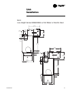
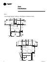
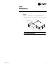
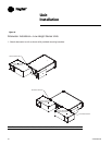
For proper service, it is recommended
that at least 36” of side clearance be
provided to service and access single-
duct and dual-duct terminals units.
Fan-powered VAV units have a plenum
inlet that must be clear of obstructions.
Allow at least 36” of clearance in front
of the side access and plenum opening.
Low-height fan-powered terminals
require the same plenum clearance
requirement that applies to the
standard fan-powered units. However
the access to the internal components
is located on the bottom of the unit.
It is also recommended that 6” of
clearance be provided to the top and
bottom of all the units.
Note: The minimum clearance for
controls and heater controls should be
36” for all models except units with 575-
volt electric heaters, which require 48” of
clearance. NEC and/or local codes
override all clearance requirements.
Actuator Mounting
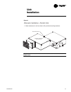
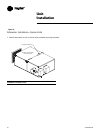
Trane offers a factory-mounted actuator
with a 90-second drive time. The
actuator drives 1 degree per second. A
field-installed actuator may be used if
desired. The actuator shaft has a ½-inch
diameter and is designed to travel
clockwise to close the damper and
counter-clockwise to open the damper.
There is an indicator on the end of the
actuator shaft that can be used to
determine the position of the damper.
Unit
Installation
Equipment Damage
Note: When installing or replacing the
actuator tighten the actuator set screw
per the manufacturer’s instructions.
Failure to follow the manufacturer’s
specifications may result in unit
malfunction.
CAUTION
CAUTION


