60 WSHP-SVX01D-EN
WARNING
Hazardous
Voltage!
Disconnect all electric power,
including remote disconnects
before servicing. Follow proper
lockout/tagout procedures to
ensure the power can not be
inadvertently energized. Failure to
disconnect power before
servicing could result in death or
serious injury.
The following steps were sequenced
to aid in the installation and mating of
a water side economizer to a water-
source heat pump (GEH 1/2 to 5 ton).
1 Remove the control side service
panel of the water-source heat
pump unit.
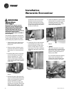
2 Remove rubber isolation grom-
mets from the return-air section.
Place them in a convenient loca-
tion.
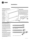
3 Attach ducted panel to the water-
source heat pump unit with six
factory provided Torx
®
head
screws. This panel is shipped
loose with the water-source heat
pump but must be field installed
to the unit.
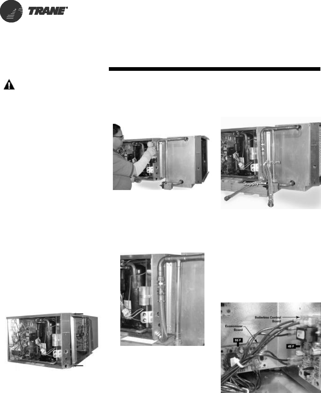
Step 3
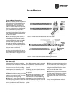
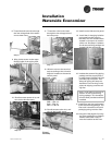
4 Attach the water side economiz-
ing unit to the ducted panel of the
water-source heat pump with 10-
factory provided Torx head
screws. The economizing pack-
age fits to the outside of the of the
water-source heat pump. Trane
recommends the mating of the
systems be made via 3-screws
spaced evenly across the top,
3-screws spaced evenly across
the bottom (installed immediate-
ly after hanging the unit), and 2-
screws on each side.
Step 4
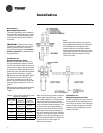
5 Install the 18-inch steel braided
hose between the upper most
piping connection of the econo-
mizer, and the water-in of the
heat pump. The hose is shipped
loose with the water-side econo-
mizer.
Step 5
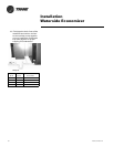
6 Install the SUPPLY and RETURN
hoses to the (1) 2-position valve’s
threaded connection (2) water-
out threaded connection of the
water-source heat pump.
Step 6
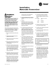
7 VERIFY
The control board for the water
side economizer is located at the
back of the control box. The tem-
perature rating of this board is
factory set to 55ºF.
For units with boilerless (electric
heat) control and water side
economizer, the boilerless con-
trol board is factory set to 45ºF.
Step 7
Installation
Waterside Economizer


