WSHP-SVX01D-EN 51
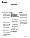
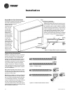
Sound Attenuation Pad
For sound sensitive installations, a vi-
bration pad (field provided) should be
placed beneath the horizontal or verti-
cal equipment. For the horizontal unit,
the pad should be approximately
twice the size of the unit foot print. For
the vertical unit, the pad should be 1/2"
(12.7 mm) thick, and equal to the over-
all unit foot print.
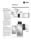
Hanging the Horizontal Unit
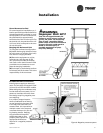
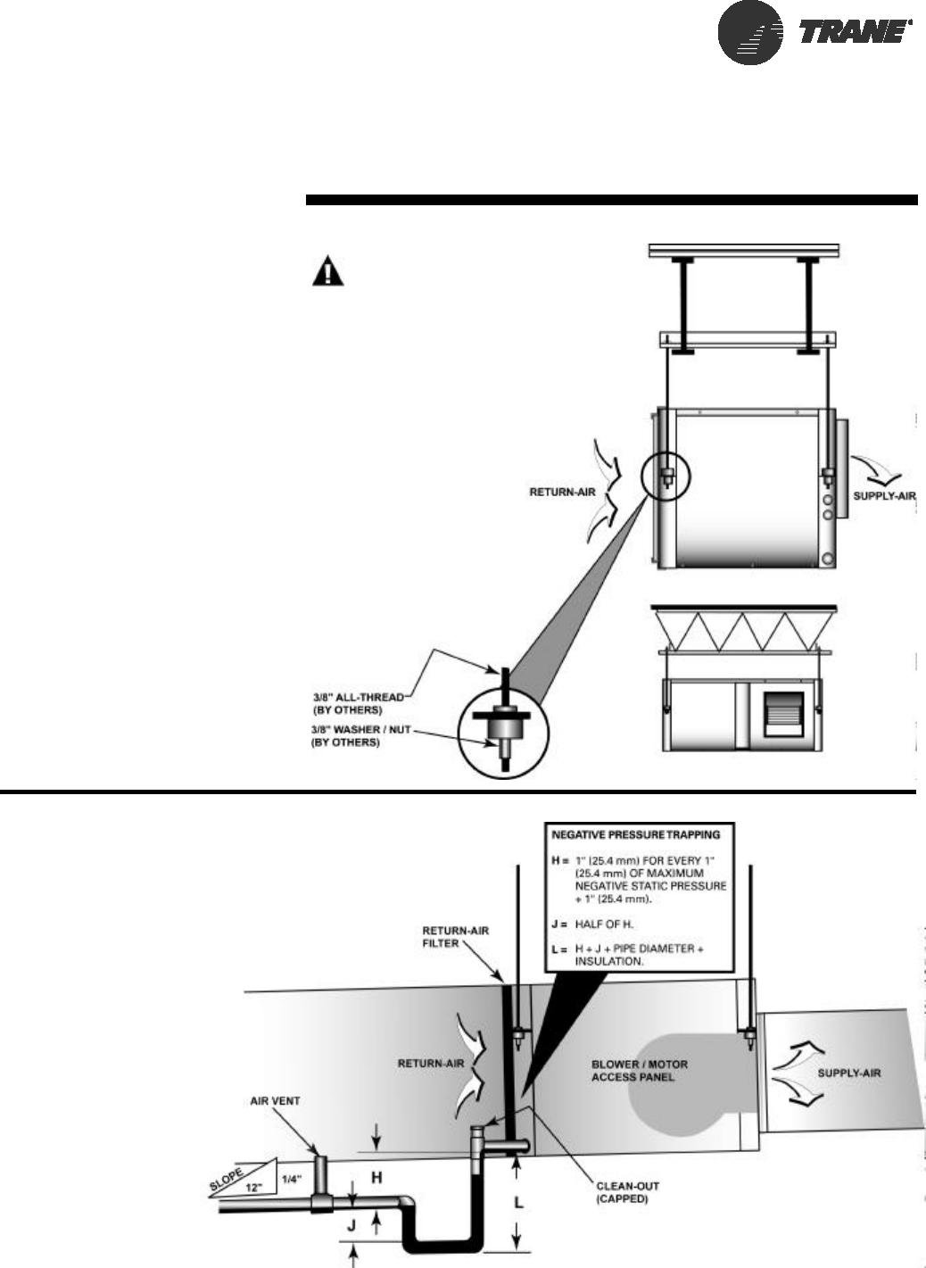
To hang the horizontal configuration:
(1) Install the hanging isolators (locat-
ed in the return-air section of the unit)
into the four hanging brackets.
(2) Secure the equipment to a joist,
concrete, etc. with the use of 3/8"
(9.7 mm) field provided (all-thread)
rod. Each corner should contain field
provided nuts and washers to com-
plete the hanging installation.
(3) Unit slope or pitch should conform
to national and local codes. This is the
responsibility of the contractor.
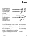
Condensate Drain Connection
Install proper trapping to the equip-
ment. The unit drain connection is 3/4"
(19 mm) for all GEH and GEV models.
When designing the condensate trap
for the water-source system, it’s im-
portant to consider the unit’s draw-
thru design requiring negative pres-
sure trapping.
In a properly trapped system,
when condensate forms during
normal operation, the water level
in the trap rises until there is a
constant flow. It is imperative to
maintain water in the trap and
not allow the trap to dry out dur-
ing heating season. Keeping
trap primed at all times will
enable the water to flow
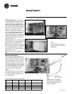
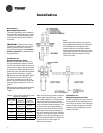
properly. See Figure 6 for
appropriate dimensions
required in a negative pressure
system.
Installation
WARNING
Improper Unit Lift!
Test lift unit approximately 24
inches to verify proper center of
gravity lift point. To avoid drop-
ping of unit, reposition lifting
point if unit is not level. Failure to
properly lift unit could result in
death or serious injury or
possible equipment or prop-
erty-only damage.
Figure 6: Negative pressure system


