


37CG-PRC007-EN
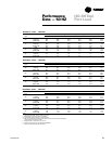
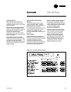
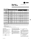
Table ED-1 — Electrical Data
Unit Wiring Motor Data
Model Nameplate Voltage Max Fuse Rec. Dual Compressor (Ea) Fans (Ea)
Tons Number Voltage Range MCA Size Element Qty. RLA LRA Qty KW FLA
CGA120B1 208-230/60/1 187-254 74 100 2 30.0 169 1 .95 6.0
CGA120B3 208-230/60/3 187-254 38.4 50 2 14.4 128 1 .95 6.0
10
CGA120B4 460/60/3 414-506 24.1 30 2 9.5 63 1 .95 2.7
CGA120BW 575/60/3 518-632 18.4 25 2 7.3 49 1 .95 2.0
CGA180B3 208-230/60/3 187-254 66 90 2 26.6 208 2 1.03 3.1
15
CGA180B4 460/60/3 414-506 35 45 2 14.3 91 2 1.03 1.6
CGA180BW 575/60/3 518-632 28 35 2 11.3 68 2 1.03 1.2
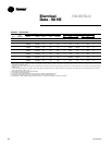
200/60/3 180-220 98 125 110 2 39.4 269 2 0.9 4.1
230/60/3 208-254 98 125 110 2 39.4 251 2 0.9 4.1
20 CGAF-C20
460/60/3 416-508 44 60 50 2 17.2 117 2 0.9 1.8
575/60/3 520-635 33 45 40 2 13.2 94 2 0.9 1.4
200/60/3 180-220 124 175 150 2 39.3,56.9 269,409 3 0.9 4.1
230/60/3 208-254 124 175 150 2 39.3,56.9 251,376 3 0.9 4.1
25 CGAF-C25
460/60/3 416-508 56 80 70 2 17.1,25.4 117,178 3 0.9 1.8
575/60/3 520-635 44 60 50 2 13.8,20.2 94,143 3 0.9 1.4
200/60/3 180-220 146 200 175 2 56.9 409 4 0.9 4.1
230/60/3 208-254 146 200 175 2 56.9 376 4 0.9 4.1
30 CGAF-C30
460/60/3 416-508 65 80 80 2 25.1 178 4 0.9 1.8
575/60/3 520-635 51 70 60 2 19.9 143 4 0.9 1.4
200/60/3 180-220 187 225 200 4 39.4 269 4 0.9 4.1
230/60/3 208-254 186 225 200 4 39.4 251 4 0.9 4.1
40 CGAF-C40
460/60/3 416-508 82 90 90 4 17.2 117 4 0.9 1.8
575/60/3 520-635 62 70 70 4 13.2 94 4 0.9 1.4
200/60/3 180-220 224 250 250 4 35.5,55.5 269,409 6 0.9 4.1
230/60/3 208-254 223 250 250 4 35.5,55.5 251,376 6 0.9 4.1
50 CGAF-C50
460/60/3 416-508 98 110 110 4 15.5,24.2 117,178 6 0.9 1.8
575/60/3 520-635 77 90 90 4 12.4,19.4 94,143 6 0.9 1.4
200/60/3 180-220 270 300 300 4 56.9 409 6 0.9 4.1
230/60/3 208-254 269 300 300 4 56.9 376 6 0.9 4.1
60 CGAF-C60
460/60/3 416-508 120 125 125 4 25.4 178 6 0.9 1.8
575/60/3 520-635 95 110 100 4 20.2 143 6 0.9 1.4
Notes:
1. MCA: Minimum Circuit Ampacity is 125% of the largest compressor RLA, plus 100% of the other compressor(s) RLA, plus the sum of the condenser fan FLA, plus any other
load rated at 1 AMP or more
2. Maximum Fuse Size: 225% of the largest compressor RLA, plus 100% of the other compressor(s) RLA, plus the sum of the condenser fan FLA, plus any other load rated at 1
AMP or more
3. Recommended Dual Element Fuse Size: 150% of the largest compressor RLA plus 100% of the other compressor(s) RLA plus the sum of the condenser fan FLA plus any
other load rated at 1 AMP or more.
4. RLA: Rated in accordance with UL standard 1995.
5. Local codes may take precedence.
6. All units are across the line starting. Compressors will never start simultaneously.
7. One 115/60/1, 15 AMP jobsite provided power connection is required to operate the evaporator heat tape.
Load Definitions
LOAD1 = Current of the largest motor —
compressor or fan motor
LOAD2 = Sum of the currents of all
remaining motors
LOAD3 = Current of electric heaters
LOAD4 = Any other load rated at 1 amp
or more
MCA = (1.25 x LOAD1) + LOAD2 +
LOAD4
MOP = (2.25 x LOAD1) + LOAD2 +
LOAD4
Electrical
Data - 60 HZ
Select a fuse rating equal to the MOP
value. If the MOP value does not equal a
standard fuse size as listed in NEC 240-6,
select the next lower standard fuse
rating.
NOTE: If selected MOP is less than the
MCA, then reselect the lowest standard
maximum fuse size which is equal to or
larger than the MCA, provided the
reselected fuse size does not exceed 800
amps.
RDE = (1.5 x LOAD1) + LOAD2 +
LOAD4
Select a fuse rating equal to the RDE
value. If the RDE value does not equal a
standard fuse size as listed in NEC 240-6,
select the next higher standard fuse
rating.
NOTE: If the selected RDE is greater than
the selected MOP value, then reselect
the RDE value to equal the MOP value.
DSS = 1.5 x (LOAD1 + LOAD2 +
LOAD3 + LOAD4)
Select a disconnect switch size equal to
or larger than the DSS value calculated.
(10–60 Ton)