CG-PRC007-EN12
point and adequate ethylene glycol
concentration for safe operation.
The maximum catalog leaving solution
temperature from the evaporator is 65°F
for outdoor ambients up to 115°F. High
leaving water temperatures exceeding
this may result in excessive suction
temperatures and, therefore, inadequate
motor cooling. For applications requiring
high leaving water temperatures, contact
your local Trane sales office for
suggested alternatives.
The maximum water temperature that
can be circulated through an evaporator,
when the unit is not operating, is
108°F (100°F for CGA 8, 10, 12½ and 15
ton chillers). The evaporator becomes
thermal stress limited at these
temperatures.
2
Supply Water Temperature Drop
The performance data for Trane chillers is
based on a chilled water temperature
drop of 10°F. Temperature drops outside
this range will result in unit performance
that differs from that cataloged. For
performance data outside the 10°F range
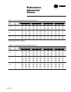
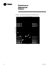
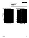
see the “Performance Adjustment
Factors” section in this catalog. Chilled
water temperature drops from 6 to 18°F
(8 to 12°F in CGA units) may be used as
long as minimum and maximum water
temperature and minimum and
maximum flow rates are not violated.
Temperature drops outside 6 to 18°F (8
to 12°F in CGA units) are beyond the
optimum range for control and may
adversely affect the controller’s
capability to maintain an acceptable
supply water temperature range.
Further, temperature drops of less than
6°F may result in inadequate refrigerant
superheat. Sufficient superheat is always
a primary concern in any direct
expansion refrigeration system and is
especially important in a package chiller
where the evaporator is closely coupled
to the compressor. When temperature
drops are less than 6°F, an evaporator
runaround loop may be required.
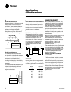
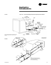
TYPICAL WATER PIPING
All building water piping must be
flushed prior to making final connections
to the chiller. To reduce heat loss and
prevent condensation, insulation should
be applied. Expansion tanks are also
usually required so that chilled water
volume changes can be accommodated.
A typical piping arrangement is shown
on the following page.
WATER VOLUME IN THE LOOP
(MINIMUM LOOP TIME)
The volume of water in the loop is critical
to the stability of system operation. The
minimum required water volume is
dependant on the chiller controller and
system GPM. Water volumes less than
the minimum required for the system
can cause nuisance problems including
low pressure trips and freezestat trips.
The cause of these trips is “Short Water
Loops”.
The minimum required water volume
(as a function of loop time and GPM) is
as follows:
CGAF: Minimum Loop Volume = GPM
x 3 Minute Loop Time
CGA: Minimum Loop Volume = GPM
X 5 Minute Loop Time
If the loop piping does not contain
enough volume, then a tank should be
added so that the equations hold true.
Generally, the more the loop volume the
greater the system stability and
controllability.
EXAMPLE: CGAFC50 with 100 gpm.
Minimum Loop Volume =
GPM x 3 Minute Loop Time
Minimum Loop Volume = 100 x 3
300 Gallon Minimum Loop Volume
If a chiller is attached to an on/off load
such as a process load, it may be difficult
for the controller to respond quickly
enough to the very rapid change in
return solution temperature. This
condition may result in freezestat or low
temperature trips. In this case, it may be
necessary to add a mixing tank in the
return line.
MULTIPLE UNIT OPERATION
Whenever two or more units are used
on one chilled water loop, Trane
recommends that their operation be
controlled from a single control device,
such as a Trane Tracer system. The
“Stand-alone” alternative is the DDC
Chiller Sequencer.
1
Series Operation
Some systems require large chilled
water temperature drops (16 to 24°F). For
those installations, two units with their
evaporators in series are usually
required. Control of the units should be
from a common temperature sensor to
prevent the separate unit controls from
fighting one another and continually
hunting. It is possible to control water
temperature from the two individual unit
controls, but a common temperature
controller provides a positive method for
preventing control overlap, more closely
matching system load and simplifying
compressor lead-lag capability.
2
Parallel Operation
Some systems require more capacity or
standby capability than a single machine
can provide. For those installations, two
units with their evaporators in a parallel
configuration are typical. The only
effective way of controlling two units in
parallel is with a single temperature
controller. For further information,
please contact Trane Applications.
Application
Considerations


