


CG-PRC007-EN32
If compressor number one can’t satisfy
the cooling demand, WTT’s second stage
switch closes, allowing power to pass
through the CWFIR contacts, the DBC,
the ASCT2, the RR2 contacts, the LPC02,
and the HPC02 to energize the CC2 coil.
This starts compressor number two and
outdoor fan number two.
LOW AMBIENT OPERATION
Field Installed Head Pressure Control
Accessory
Standard units will operate in outdoor
ambient temperatures down to the
values shown in the “General Data”
section of this catalog. This accessory
will enable units to operate down to
much lower temperature extremes (see
“General Data” section of this catalog).
Head pressure control for CGA units is
regulated by means of a field-installed
head pressure accessory which varies
condenser fan speed in relation to
discharge pressure.
When discharge pressure is 270 psig or
higher, the condenser fan runs at full
speed. At pressures between 270 psig
and 180 psig, the fan speed is adjusted
(increased or decreased) in direct relation
to the pressure, with minimum fan speed
(10 percent of rated motor rpm)
occurring when the pressure reaches 180
psig. At pressures below 180 psig, the fan
will not run. When discharge pressure
rises to 180 psig, the fan will start and run
at the reduced speed. Fan speed will
continue to increase, as the pressure
increases, until full speed is reached at
270 psig.
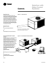
SEQUENCE OF UNIT OPERATION
Refer to the unit wiring schematic pasted
to the inside of the control panel cover
when reviewing the control sequence
described below.
Refer to the legend on the previous page
for an explanation of the abbreviations
used in this sequence.
10-Ton Operation
With fused disconnect switch closed,
power is supplied to the crankcase
heaters and the 24-volt control circuit.
Starting the chilled water pump closes
the CWPS auxiliary contacts and
completes the flow switch.
When the water temperature rises above
the WTT’s set point, its first stage switch
closes, allowing power to pass through
CWPS auxiliary contacts, the flow switch,
the LTC, the ASCT1, the RR1 contacts, the
LPC01, and the HPC01 to energize the
CC1 coil. This starts compressor number
one and the outdoor fan.
If compressor number one can’t satisfy
the cooling demand, WTT’s 2nd stage
switch closes, allowing power to pass
through the CC1 auxiliary contacts, the
DBC, the ASCT2, the RR2 contacts, the
LPC02, and the HPC02 to energize the
CC2 coil which starts compressor
number two.
15-Ton Operation
With fused disconnect switch closed,
power is supplied to the crankcase
heaters, and the 24-volt control circuit.
Starting the chilled water pump closes
the CWPS auxiliary contacts and
completes the flow switch, allowing
power to pass through the LTC to
energize the CWFIR.
When the water temperature rises above
the WTT’s set point, its first stage switch
closes, allowing power to pass through
the CWFIR contacts, the ASCT1, the RR1
contacts, the LPC01, and the HPC01 to
energize the CC1 coil. This starts
compressor number one and outdoor
fan number one.
Controls (10, 15 Ton)