


15CG-PRC007-EN
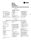
Model
Number
Description
CGA 120 B 3 00 B A
123 456 7 8 9,10 11 12
DIGIT 10 — Leaving Solution Set point
0 =Standard Expansion Valve
40-60°F Leaving Water
(CGA100 & CGA120 models)
20-60°F Leaving Solution
(CGA150 & CGA180 Models)
V = Nonstandard Expansion Valve
20-39°F Leaving Solution
(CGA100 & CGA120 models)
DIGIT 11 — Minor Design Change
A = First, B = Second, etc.
DIGIT 12 —Service Digit
DIGIT 1,2,3 — Unit Type
CGA = Air-Cooled Cold Generator
™
DIGITS 4,5,6 — Nominal Capacity (MBh)
100 = 8 Tons (50 Hz Model only)
120 = 10 Tons (60 Hz Model only)
150 = 12.5 Tons (50 Hz Model Only)
180 = 15 Tons (60 Hz Model Only)
DIGIT 7 — Major Design Change
(Number of Refrigerant Circuits/Number of
Compressors)
B = 2 Refrigerant Circuits/2 Compressors
DIGIT 8 — Voltage
1 = 208-230/60/1
(Available — CGA120 Only)
3 = 208-230/60/3
4 = 460/60/3
W= 575/60/3
D = 380-415/50/3
DIGIT 9 — Factory Installed Options
0 = No Options
H = Hot Gas Bypass
C = Black Epoxy Coil Standard Deviation
K = Hot Gas Bypass & Black Epoxy Coil
S = Special
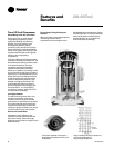
10, 15 Tons
20–60 Tons
DIGIT 1,2 — Unit Model
CG = IntelliPak
™
Air-Cooled Chiller
DIGIT 3 — Unit Type
A = Air-Cooled Condensing
DIGIT 4 — Development Sequence
A, B, C, etc.
DIGIT 5,6,7 — Nominal Capacity
C20 = 20 Tons
C25 = 25 Tons
C30 = 30 Tons
C40 = 40 Tons
C50 = 50 Tons
C60 = 60 Tons
DIGIT 8 — Voltage & Start Characteristics
E = 200/60/3 XL
F = 230/60/3 XL
4 = 460/60/3 XL
5 = 575/60/3 XL
9 = 380/50/3 XL
D = 415/50/3 XL
S = Special
DIGIT 9 — Factory Input
A = Standard
CG A F C40 4 A A A 1 A A A A A 0 0 0 0 0 0 0 0
1
12 3 4 567 8 9 10 11 12 13 14 15 16 17 18 19 20 21 22 23 24 25
DIGIT 10 — Design Sequence
A = First
B = Second
Etc...
DIGIT 11 — Leaving Solution Set point
A = 40-50 Deg. F w/o Ice Machine
B = 30-39 Deg. F w/o Ice Machine
D = 51-65 Deg. F w/o Ice Machine
E = 20-29 Deg. F w/o Ice Machine
1 = 40-50 Deg. F with Ice Machine
2 = 30-39 Deg. F with Ice Machine
3 = 51-65 Deg. F with Ice Machine
4 = 20-29 Deg. F with Ice Machine
S = Special
DIGIT 12 — Agency Approval
1 = UL/CSA
0 = None
DIGITS 13-25 — Miscellaneous
A = Trane Communication Interface
(TCI) Module
B = No Unit Heat Tape (50 Hz Only)
C = Compressor Current Sensing (CSM)
D = Unit Mounted Disconnect Switch
Nonfused
E = Unit Isolators Neoprene
F = Unit Isolators Spring
G = Superheat/Sub-Cooling
H = Hot Gas Bypass
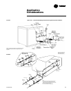
The following items can be ordered for
separate shipment —
• Unit Isolators — Neoprene*
• Unit Isolators — Spring*
• Electronic Low Ambient Damper(s)
• Trane Communication Interface Module
(TCI)
• Generic B A S Module (GBAS)
• (0-5 volt Analog Input/Binary Output)
• Generic B A S Module (GBAS)
• (0-10 volt Analog Input/Output)
• Remote Human Interface
• Remote Set point Potentiometer
• Zone Sensor (Chilled Solution Reset)
• Inter-Processor Communication Bridge
(IPCB)
*Unit size must be specified when ordering
this item.
J = Generic B A S Module
(0-5 v Input, Binary Output)
M = Remote Human Interface
N = Generic B A S Module
(0-10 v Analog)
P = Remote Set point Potentiometer
Q = Zone Sensor — Chilled Solution
Reset
V = Copper Fin Condenser Coils
W= Electronic Low Ambient Damper(s)
Y = Inter-Processor Communication
Bridge (IPCB)
9 = Packed Stock Unit
1. The service digit for each model number contains 25
digits; all 25 digits must be referenced.