


8
Providing a brighter solution.™
CA8900 Z-Wave
®
Thermostat Installation Guide
G
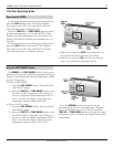
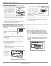
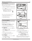
4 Wire Heat Pump
w/o Aux Heat +C
From
Furnace
RH
C
O
Y
B
WIRES:
C B or O Y RH G
CA8900 Terminals
Y
B
RH
G
C
HEAT PUMP SYSTEM
O
C B O
W
2
W Y RH RC G A
or
or
Connect 1. O wire to the O terminal or B wire to the B terminal
on the CA8900. (If you have both O and B, connect O wire to O
terminal
DO NOT connect B to B terminal. (See page 10 Trane for the B
wire terminal.) This connects the change-over valve.
Connect the 2. Y wire to Y on the CA8900. This connects the Com-
pressor.
Connect the 3. R (or RH) wire to RH on the CA8900. This connects
to the 24vac power.
Connect the 4. G wire to the G terminal on the CA8900. This con-
nects the Fan.
Connect the 5. C wire to the C terminal on the CA8900. This con-
nects 24vac power.
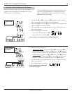
Set Config jumpers as shown.6.
Your system is now connected. Continue on page 9.
4 Wire
Heat
Pump
w/o
Aux
+C
1 2
3
4 5
C B or O W2 Y R H G
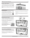
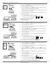
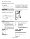
5 Wire
Heat Pump
w/ Aux Heat
+C
From
Furnace
RH
C
O
or
W2
B
G
Y
WIRES:
CA8900 Terminals
Y
W2
B
R
G
C
HEAT PUMP SYSTEM
O
C B O
W2
W
Y RH RC G A
OPTIONAL POWER
or
or
Connect 1. O wire to the O terminal or B wire to the B terminal on the
CA8900. If you have both O and B, connect O wire to O terminal.
DO NOT connect B to B terminal. See page 10 Trane for B
wire terminal.
Connect the 2. W2 wire to W2 on the CA8900.
Connect the 3. Y wire to Y on the CA8900.
Connect the 4. R wire to RH on the CA8900.
Connect the 5. G wire to G on the CA8900.
Connect the 6. C wire to the C terminal on the CA8900. This con-
nects 24vac power.
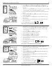
Set Config jumpers as shown.7.
Set jumper 5 if you have Gas 8.
or Oil aux heat.
Your system is now connected. Continue on page 9.
1 2
3
4 5
5 Wire
Heat
Pump
w/ Aux
Heat +C
G
RH
C W2 W Y R H G
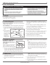
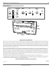
1 stage Cool
2 stage Heat
+C
From
Furnace
C
W
Y
W2
WIRES:
CA8900 Terminals
W2
W Y
RH
G
C
HVAC SYSTEM
C B O
W
2
W
Y RH RC G A
OPTIONAL
POWER
Connect the 1. W wire to the W terminal and W2 to W2 on the
CA8900. This connects 2 stages of heat.
Connect the 2. Y wire to the Y terminal wire on the CA8900. This
connects cool.
Connect the 3. RH or R wire to the RH terminal on the thermostat. This
connects the Heater/Cool Power.
Connect the 4. G wire to the G terminal on the Thermostat. This
connects to the Fan.
Connect the 5. C wire to the C terminal on the CA8900. This con-
nects 24vac power
Set Config jumpers as shown.6.
If you have Electric heat, set - 1A.
If you have Gas or Oil, set - 1B.
Your system is now connected. Continue on page 9.
2 Stage
Heat and
1 Stage
Cool +C
2
3
4 5
1
A
B