


5
Providing a brighter solution.™
CA8900 Z-Wave
®
Thermostat Installation Guide
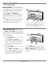
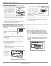
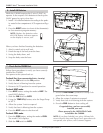
Separate front from back of 1.
unit. Grasp the thermostat
and pry the body away from
the base, lift up to remove
the body from the base. Set
aside the control unit.
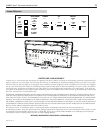
Hold the base against the 2.
wall, with the wires coming
through the opening below the terminal block.
Thread wires through the hole in the thermostat 3.
base. Take care not to “short” wires.
Position the base for best appearance. Mark the 4.
holes in pencil for drilling or mount directly to the
wall with the two screws provided.
Terminal
Block
Hole in
wall
Thermostat Base
4 – Mount the CA8900 Thermostat
Control unit
[body]
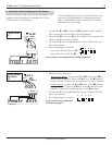
Please follow these guidelines for safe and secure wire
connections.
Use the Step-By-Step diagram as •
your guide.
Strip 3/8” of the wire and form as •
shown
Take care not to damage the labels for each wire in •
handling.
Fan wires out as illustrated with CA8900 below the •
wall opening.
Wires will dress behind the CA8900 and up over the •
terminal area.
Do not bunch wires behind CA8900. Feed slack •
back into the wall opening.
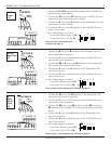
Connect labeled wires only to a terminal with cor-•
responding letter.
CAUTION: Do not allow wires to touch each other
or parts on thermostat.
Insert the wire in the terminal and tighten the screw •
securely.
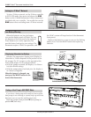
You will need to •
set Configura-
tion Jumpers
per the Step-By-
Step diagram. A
Before You Connect Wires
Jumpers
1 2
3
4 5
Which wires do you have?
Determine which step-by-step wiring diagram you •
should use from the next pages. Make sure your
wires are labeled. This may require you to find the
‘other end’ connection for each wire on your heat-
ing or air conditioning equipment and read the label
there.
You must have a wire marked “C” (24VAC) for the •
CA8900 to operate. Without the 24VAC power, the
CA8900 will run on its back-up batteries for just a
few days.
Jumpers
1 2
3
4 5
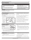
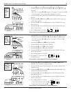
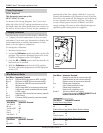
If you are mounting the 5.
base to drywall or if you
are using the old mount-
ing holes, use the plastic
anchors provided. Drill
a 3/16-in. (4.8mm) hole
for the insert at each
screw location, and then
mount the base.
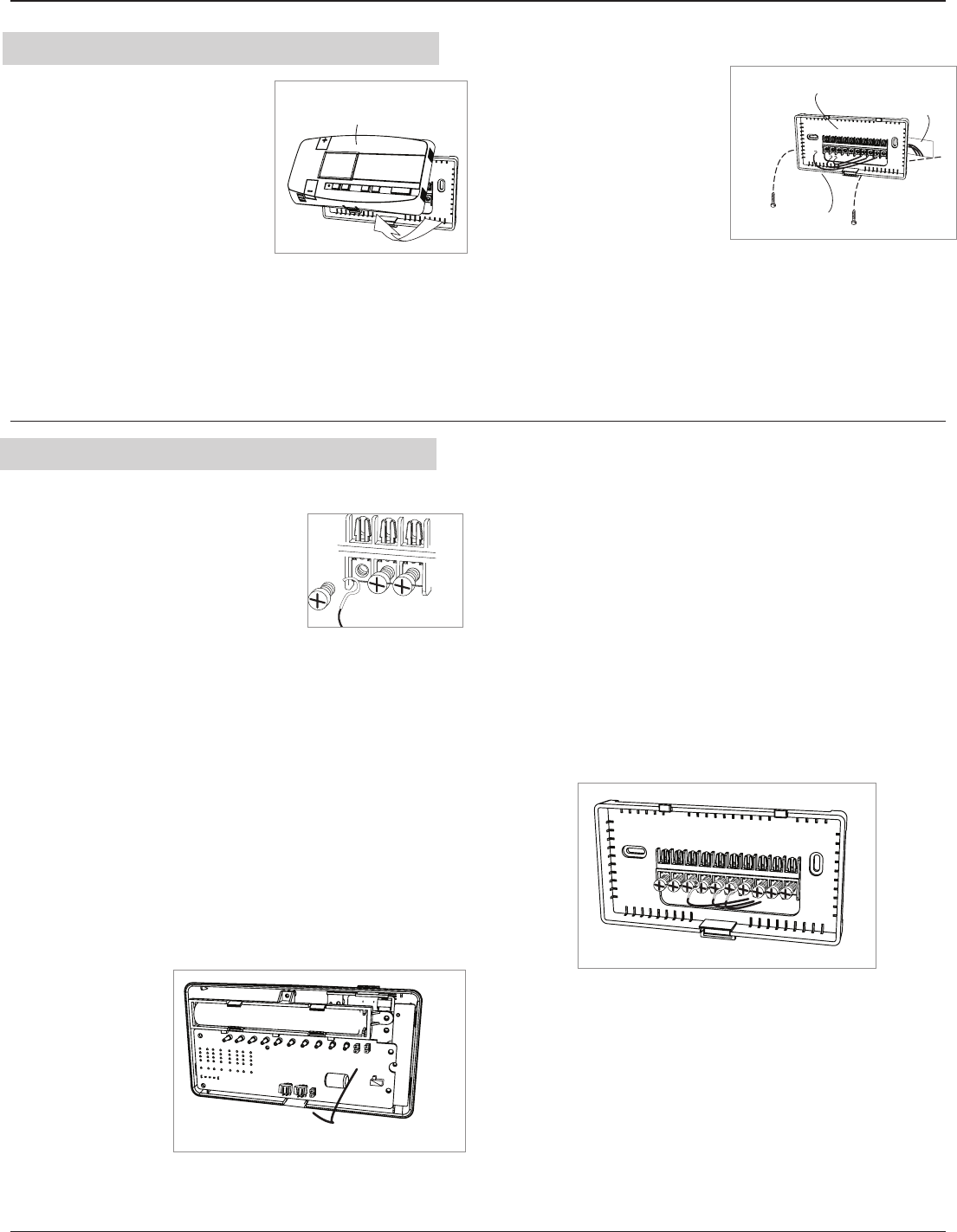
Thread wires through the hole in the thermostat 6.
base.
Leave wires loose in the opening, take care that 7.
they do not “short.”