


10
Providing a brighter solution.™
CA8900 Z-Wave
®
Thermostat Installation Guide
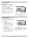
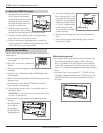
24VAC Required!
This thermostat must run on the
HVAC 24VAC (C) wire.
As shown in the wiring diagrams, the C wire is the
other side of the 24VAC heating transformer and can
be found where the other thermostat wires connect at
the wall or at the furnace. Do not use the common or
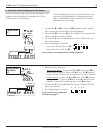
Power Requirement
Your thermostat comes from the factory calibrated to
+/- 1 degree of actual temperature. It is an accurate
instrument. If you want your thermostat to display the
same temperature as another thermometer in your
home, you can adjust its calibration.
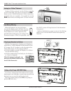
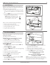
To change the calibration:
Remove the top cover.1.
Locate the 2. Calibration switch and slide it to the ON
position. The current calibration factor (+/-) of the
CA8900 will appear in the LCD display.
Push the 3. UP or DOWN arrows until the desired cali-
bration factor is reached.
Slide the 4. Calibration switch to the OFF position.
The new calibrated temperature will be displayed
on the LCD.
Changing Calibration
Calibrate
switch
OFF ON
ground side of the line voltage. With the C wire con-
nected, the thermostat will continue to work if the bat-
teries die or are removed. The batteries are for back-up
in case of power loss and only will last a few days.
In case of total power loss the NORMAL and SAVE
energy settings will return to their default settings (see
operation guide) when power is reapplied.
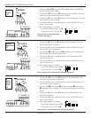
Wire Reference Guide
Your Wires Intermatic Terminal
R or V or V R RH and RC Single power for HEAT and COOL
RH or 4 RH Power for HEAT (RH not connected to RC)
RC RC Power for COOL (RH not connected to RC)
W W Heat control
W2 W2 2nd stage HEAT or heat pump auxiliary heat
? A 3rd wire for zoned hot water heat (see zoned)
Y Y COOL control
Y2 2nd stage COOL control (do not connect; tape off)
G or F G FAN control
C or X C Common 24VAC power (to power thermostat)
Your Wires Intermatic Terminal
E Emergency heat (do not connect, tape off)
L System monitor (do not connect, tape off)
T Outdoor sensor (do not connect, tape off)
B or B Heat pump changeover
(cool to heat, powered in heat)
O O Heat pump changeover
(heat to cool, powered in cool)
B and O If there are both B and O wires
(Trane pump products). DO NOT CONNECT B to B
terminal, connect B to C terminal.
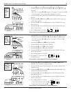
Your Wires Intermatic Terminal
V or VR or R RH
M or Y Y
Y or W or W2 W2
F or G G
R or O O
X or X2 or C C
Lennox Heat Pump
Trane Products (Amer Std)
Your Wires Intermatic Terminal
B C
W or W1 W2
Zoned Systems
Your Wires Intermatic Terminal
2 wire Zoned Hot Water
R RH
W W
3 Wire Zoned Hot Water Motor Driven Valves
R RH
W W
Y (the 3rd wire) A
3 Wire Zoned Hot Water Solenoid Valves
R RH
W A
Y (the 3rd wire) W