


6
Providing a brighter solution.™
CA8900 Z-Wave
®
Thermostat Installation Guide
From
Furnace
C
W
C W RH
RH
2 Wire
Heat +C
Go To Page 8
WIRES:
W
R
C
C B O
W2
W
Y RH RC G A
OPTIONAL POWER
CA8900 Terminals
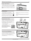
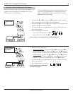
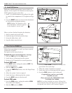
Connect the 1. R (or RH) wire to the RH terminal on the CA8900.
This connects the Heater Power to the thermostat.
Connect the 2. W wire to the W on the CA8900. This connects the
heater control line to the CA8900.
Connect the 3. C wire to the C terminal on the CA8900. This con-
nects 24vac power.
Set Config jumpers as shown. 4.
If you have Electric heat, set - 1A.
If you have Gas or Oil, set - 1B.
Your system is now connected. Continue on page 9.
2 WIRE HEAT
+C
1
3
4 5
2
A
B
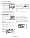
Find the reference page with your wiring diagram and
jumper set-up information. Remember, the C wire
[24vac power] is not optional.
5 – Find and Use the Set-Up Diagram for Your System
If your combination of wires is not shown here, you
can use the Wiring Reference Guide beginning on
page 11 to determine your connections, or contact
Customer Service for help.
Go To Page 15
From
Furnace
W
RH
A
W RH A
3 Wire
Zoned
Hot Water +C
WIRES:
C
WC
R A
Motor Valve
C B
O
W
2
W
Y RH RC G A
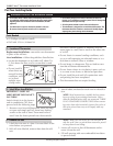
CA8900 Terminals
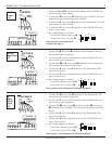
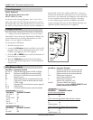
Based on your valve type:1.
Motor driven Valve - - Connect the R (or RH) wire to the RH ter-
minal on the CA8900. Connect the W wire to the W terminal
on the CA8900. Connect the remaining wire to the A terminal.
Solenoid valve - -Connect the R (or RH) wire to the RH terminal
on the CA8900. Connect the W wire to the A terminal on the
CA8900. Connect the remaining wire to the W terminal.
Connect the 2. C wire to the C terminal on the CA8900. This con-
nects 24vac power.
Set Config jumpers as shown.3.
Your system is now connected.
Continue on page 9.
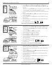
3 Wire Zoned
Hot Water
+C
1 2
3
4 5